
Owner's Manual

Cover
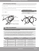
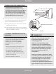
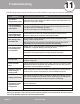
Outdoor Unit
Wiring Diagram
is located on
the inside of the
wire cover on
the outdoor unit.
Fig. 8.2
Page 34
mrcool.com
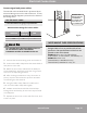
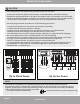
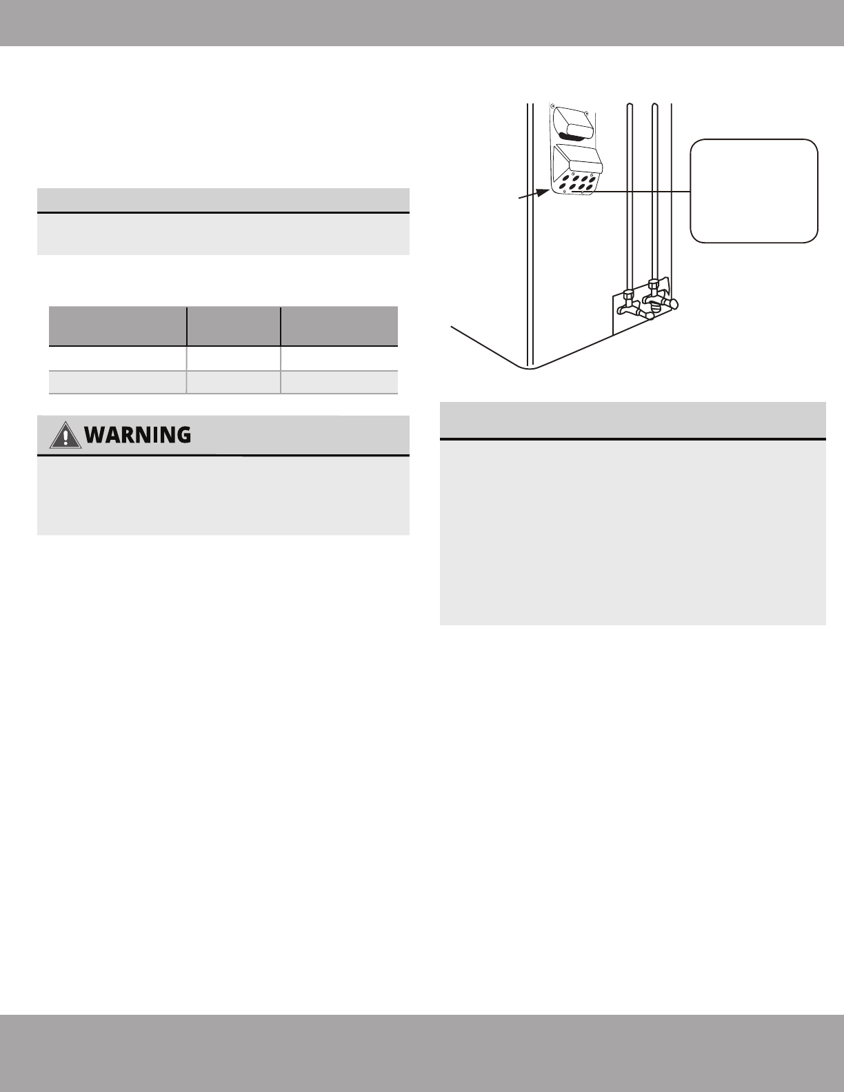
Electrical Connections
Appliance
Amps(A)
AWG
35
45
8
6
27K
36K
Model Series
Minimum Wire Gauge
for Power Cables
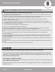
USE THE RIGHT CABLE
• See table below for gauge requirements
ALL WIRING MUST BE PERFORMED STRICTLY
IN ACCORDANCE WITH THE WIRING
DIAGRAM LOCATED AS SHOWN IN FIG 8.2.
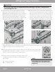
1. Unscrew the electrical wiring cover and remove it.
2. Unscrew the cable clamp below the terminal block
and place it to the side.
3. Match the wire colors / labels with the labels on
the terminal block, and firmly screw the u-lug of each
wire to its corresponding terminal.
4. After checking to make sure every connection is
secure, loop the wires around to prevent rain water
from flowing into the terminal.
5. Using the cable clamp, fasten the cable to the
unit. Screw the cable clamp down tightly.
6. Insulate unused wires with PVC electrical tape.
Arrange them so that they do not touch any electrical
or metal parts.
7. Replace the wire cover on the side of the unit, and
screw it in place.
The air conditioner’s circuit board (PCB) is
designed with a fuse to provide overcurrent
protection. The specifications of the fuse are
printed on the circuit board.
EXAMPLE Indoor unit: T3.15AL/250VAC,
T5AL/250VAC, T3.15A/250VAC, T5A/250VAC, etc.
EXAMPLE Outdoor unit:
T20A/250VAC(<=18000Btu/h units),
T30A/250VAC(>18000Btu/h units), etc.
NOTE ABOUT FUSE SPECIFICATIONS
Connect signal and power cables
The outside unit’s terminal block is protected by an
electrical wiring cover on the side of the unit. A com-
prehensive wiring diagram is printed on the inside of
the wiring cover.