
Installation Guide


Page 44mrcool.com
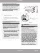
Refrigerant Piping Connection
AFTER PERFORMING GAS LEAK CHECKS
After confirming that all of the refrigerant pipe
connections points DO NOT leak, replace the
valve cover on the outside unit and wrap and
insulate the piping connections of the
indoor unit.
8
BEFORE TEST RUN
9
Using a soft brush or spray bottle, apply a soapy
water solution to all of the pipe connection points of
the indoor and outdoor units, watching to see if any
bubbles form. The presence of bubbles indicates
there is a leak.
There are two different methods to check for
gaseous leaks. Use Fig. 9.1 below as a guide for
the critical points to check for leaks.
Soap and Water Method
Leak Detector Method
If using a leak detector, refer to the device’s
operation/instruction manual for proper usage
instructions.
Gas Leak Checks
Electrical and Gas Leak Checks
IF ELECTRICAL LEAKAGE IS DETECTED
If electrical leakage is detected, turn off the
unit immediately and call a licensed
electrician to find and resolve the cause of
the leakage.
After installation is complete, confirm that all
electrical wiring has been installed in accordance
with local and national regulations, and according
to the installation manual.
Check Insulated Resistance
The insulated resistance must be more than 2MΩ.
Check Grounding Work
Measure grounding resistance by visual detection
and with a grounding resistance tester. Grounding
resistance must be less than 0.1Ω.
NOTE: This may not be required for some
locations in North America.
Check for Electrical Leakage
During the Test Run, use an electroprobe and
multimeter to perform a comprehensive electrical
leakage test.
NOTE: This may not be required for some
locations in North America.
Electrical Safety Checks
DURING TEST RUN
WARNING – RISK OF
ELECTRICAL SHOCK
ALL WIRING MUST BE INSTALLED BY A
LICENSED ELECTRICIAN AND COMPLY WITH
LOCAL, STATE, AND NATIONAL ELECTRICAL
CODES.
Fig. 9.1
Indoor unit
check points
Outdoor unit
check points
NOTE: The illustration above is for demonstration
purposes only. The actual order of the A, B, C, D,
and E valves on your system may be slightly
different from what is shown, however, the
general shape will remain the same.