Troubleshooting & Solutions Guide 4th Generation ® DIY Multi-Zone Due to updates and constantly improving performance, the information and instructions within this manual are subject to change without notice. Please visit www.mrcool.com/documentation to ensure you have the latest version of this manual.
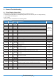
Troubleshooting Contents 1. Safety Caution .......................................................................................................3 2. General Troubleshooting ......................................................................................4 2.1 Error Display (Indoor Unit) ..............................................................................4 2.2 Error Display (Outdoor Unit) ...........................................................................6 3.
Troubleshooting Contents 8.7 PC 01(Over voltage or too low voltage protection)/PC 10(Outdoor unit low AC voltage protection)/PC 11(Outdoor unit main control board DC bus high voltage protection)/PC 12(Outdoor unit main control board DC bus high voltage protection /341 MCE error) Diagnosis and Solution......................38 8.8 PC40(Communication malfunction between IPM board and outdoor main board diagnosis and solution).....................................................................40 8.
1. Safety Caution WARNING Be sure to turn off all power supplies or disconnect all wires to avoid electric shock. While checking indoor/outdoor PCB, please equip oneself with anti-static gloves or wrist strap to avoid damage to the board. WARNING Electricity remains in capacitors even when the power supply is off. Ensure the capacitors are fully discharged before troubleshooting. Test the voltage between P and N on back of the main PCB with multimeter.
2. General Troubleshooting 2.1 Error Display (Indoor Unit) When the indoor unit encounters a recognized error on different models, 1. the running LED with flash in a corresponding series, the timer LED may turn on or begin flashing; 2. an error code will be displayed; 3. both 1 and 2.
For other errors: The display board may show a garbled code or a code undefined by the service manual. Ensure that this code is not a temperature reading. Troubleshooting: Test the unit using the remote control. If the unit does not respond to the remote, the indoor PCB requires replacement. If the unit responds, the display board requires replacement.
2.
3. Complain Record Form Complain Record Form Request No.: Date: Installation Date: Service Date: Customer Information Name Telephone No. Home Address Email Product Information Indoor Unit Model Outdoor Unit Model Serial No. of indoor unit Serial No.
Parameter Checking information by Remote controller Displaying code Displaying code meaning T1 Room temperature T2 Indoor coil temperature T3 Outdoor coil temperature T4 Ambient temperature Tb Outlet temperature of indoor coil TP Discharge temperature TH Sunction temperature FT Targeted Frequency Fr Actual Frequency IF Indoor fan speed OF Outdoor fan speed LA EXV opening steps CT Compressor continuous running time ST Causes of compressor stop.
4. Information Inquiry • To enter information inquiry status, complete the following procedure within 10 seconds: • Press LED 3 times. • Press SWING 3 times. • Finish 1 and 2 within 10 seconds, you will hear beeps for two seconds, which means the unit goes into parameter checking mode. • Use the LED (or DO NOT DISTURB) and SWING (or AIR DIRECTION) buttons to cycle through information displayed. • Pressing LED (or DO NOT DISTURB) displays the next code in the sequence.
Displayed code Displayed value Explanation T1 Room temperature T2 Indoor coil temperature T3 Outdoor coil temperature T4 Ambient temperature Tb Meaning Additional Notes 1. All displayed temperatures use actual values. -1F,-1E,-1d,-1c,- -25,-24,-23,-22, 1b,-1A -21,-20 2. All temperatures are displayed in °C regardless of remote used.
Displayed code Explanation Displayed value Meaning Additional Notes A0 A1 0 1 2 3 0-FF 4 5 6 L Reserved 2-28 5-20 - 5-25 A U T A 5 T Troubleshooting 11 -
5. Outdoor Unit Point Check Function • A check switch is included on the outdoor PCB. • Push SW1 to check the unit’s status while running. The digital display shows the following codes each time the SW1 is pushed.
17 18 19 20 Indoor unit A evaporator outlet temperature (T2BA) Indoor unit B evaporator outlet temperature (T2BB) If the temperature is lower than -9°C, the digital display Indoor unit C evaporator outlet shows “-9.” If the temperature is higher than 70°C, the digital temperature (T2BC) display shows “70.
37 EXV open angle for A indoor unit 38 EXV open angle for B indoor unit 39 EXV open angle for C indoor unit 40 EXV open angle for D indoor unit 41 EXV open angle for E indoor unit Actual data/4. If the value is higher than 99, the digital display shows single and double digits. For example, if the digital display shows “2.0”, the EXV open angle is 120×4=480p.
For key board models, Number of Presses 0 Display Remark Normal display Displays running frequency, running state, or malfunction code Display Number of indoor unit 1 Quantity of indoor units with working connection 1 1 2 2 3 3 4 4 2 Outdoor unit running mode code 3 Indoor unit A capacity 4 Indoor unit B capacity 5 Indoor unit C capacity The capacity unit is horse power.
22 Indoor unit A room temperature (T1A) 23 Indoor unit B room temperature (T1B) 24 Indoor unit C room temperature (T1C) 25 Indoor unit D room temperature (T1D) 26 Indoor unit E room temperature (T1E) 27 Indoor unit A evaporator temperature (T2A) 28 Indoor unit B evaporator temperature (T2B) 29 Indoor unit C evaporator temperature (T2C) 30 Indoor unit D evaporator temperature (T2D) 31 Indoor unit E evaporator temperature (T2E) 32 Condenser pipe temperature (T3) 33 Outdoor ambient tempe
Bit7 Bit6 Bit5 45 Bit4 Frequency limit symbol Bit3 Bit2 Frequency limit caused by IGBT radiator The display value is a hexidecimal number. Frequency limit caused by PFC For example, the digital display show Frequency limit caused by T4. 2A, then Bit5=1, Frequency limit caused by T2. Bit3=1, and Bit1=1. Frequency limit caused by T3. This means that a Frequency limit caused by T5.
6. Error Diagnosis and Troubleshooting Without Error Code WARNING Be sure to turn off unit before any maintenance to prevent damage or injury. 6.1 Remote maintenance SUGGESTION:When troubles occur, please check the following points with customers before field maintenance. No.
6.
Loose connec�ons Faulty transformer The voltage is too high or too low The remote control is powered off Broken remote control Dirty air filter Dirty condenser fins The se�ng temperature is higher/lower than the room's(cooling/hea�ng) The ambient temperature is too high/low when the mode is cooling/hea�ng Fan mode SILENCE func�on is ac�vated(op�onal func�on) Fros�ng and defros�ng frequently Inspect connec�ons - �ghten Change the transformer Test voltage Replace the ba�ery of the remote control Replace the
Heavy load condi�on Loosen hold down bolts and / or screws Bad airproof The air inlet or outlet of either unit is blocked Interference from cell phone towers and remote boosters Shipping plates remain a�ached Tighten bolts or screws Close all the windows and doors Remove the obstacles Reconnect the power or press ON/OFF bu�on on remote control to restart opera�on Remove them Others Check heat load 1.
Condenser (Outdoor) fan will not start Compressor short-cycles due to overload High discharge pressure Low discharge pressure High suc�on pressure Low suc�on pressure Unit runs con�nuously but insufficient cooling Too cool Compressor is noisy Horizontal louver can not revolve Test method / remedy Troubleshooting 22 Poor choices of capacity Contact of piping with other piping or external plate Choose AC of lager capacity or add the number of AC Rec�fy piping so as not to contact each other or wit
Low suc�on pressure High suc�on pressure Unit runs con�nuously but insufficient cooling Too cool Horizontal louver can not revolve Compressor is noisy Test method / remedy Troubleshooting 23 Low voltage Test voltage Shorted or grounded fan motor Faulty magne�c contactor for fan Check resistance with mul�meter Faulty magne�c contactor for compressor Test con�nuity of coil & contacts Test con�nuity of coil & contacts Faulty stepping motor Shorted or open capacitor Check capacitor with tester Sho
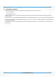
7. Quick Maintenance by Error Code If you do not have the time to test which specific parts are faulty, you can directly change the required parts according the error code. You can find the parts to replace by error code in the following table.
Part requiring replacement Error Code EC 07/ PC 08/(O) PC 44 PC 00/ (O)EC 71 /PC 46 / PC 49 PC 04 PC 01/(O)PC 10 /PC 11/PC 12 (O)PC 0F EC 51 EC 56 Outdoor fan motor x x T3 Sensor x x x x T4 Sensor x x x TP Sensor x x T2B Sensor x Reactor or inductance x x x Compressor x x x IPM module board x x x x Bridge rectifier x x x x PFC module x x x x x x Additional refrigerant x x x x x x x Electric control box x x x x x x x High pressure switch x x x
Part requiring replacement Error Code PC 40 EC 72 PC 43 PC 45 PC 03/ (O)PC 06 (O)PC 0A (O)PC 30 (O)PC 31 x Outdoor PCB Outdoor fan motor x x x x T3 Sensor x x x x x T4 Sensor x x x x x TP Sensor x x x x T2B Sensor x x x x Reactor or inductance x x x Compressor x x IPM module board x x x Bridge rectifier x x x PFC module x x Additional refrigerant x Electric control box x x x x x x x x x x x x x x x x x x x x x x x x x x x x x
8. Troubleshooting by Error Code 8.1 EH 00 / EC 51 (EEPROM parameter error diagnosis and solution) Description: Indoor or outdoor PCB main chip does not receive feedback from EEPROM chip. Recommended parts to prepare: • Indoor PCB • Outdoor PCB Troubleshooting and repair: EH 00 EC 51 Shut Shut off off the the power power supply supply and and turn turn itit on on 22 minutes minutes later. later.
8.2 EL 01 (Indoor and outdoor unit communication error diagnosis and solution) Description: Indoor unit does not receive the feedback from outdoor unit during 110 seconds and this condition happens 4 times continuously.
Indoor / outdoor units communication error Start: Power off, then Power on the A/C by the Breaker reconnect the power wire). Is it still displaying the error code ? Yes Check wiring on the outdoor and indoor terminal follow the wiring diagram. Is all connecting correctly? Reconnect the wiring No No Reconnect the wiring Yes Turn on all indoor units by remote controller.
Remarks: • Use a multimeter to test the resistance of the reactor which does not connect with capacitor. • The normal value should be around zero ohm. Otherwise, the reactor must have malfunction. Note: The picture and the value are only for reference, actual condition and specific value may vary.
8.3 EH 03 / EC 07 (Fan Speed Is Operating Outside of Normal Range) / EC 71 (Over Current Failure of Outdoor DC Fan Motor) Diagnosis and Solution Description: When indoor / outdoor fan speed keeps too low or too high for a certain time, the LED displays the failure code and the AC turns off. Recommended parts to prepare: • Connection wires • Fan assembly • Fan motor • PCB Troubleshooting and repair: Power off, then restart the unit after 2 minutes.
Index: 1. Indoor or Outdoor DC Fan Motor(control chip is in fan motor) Power on and when the unit is in standby, measure the voltage of pin1-pin3, pin4-pin3 in fan motor connector. If the value of the voltage is not in the range showing in below table, the PCB must has problems and need to be replaced. • DC motor voltage input and output (voltage: 220-240V~): No. Color Signal Voltage 1 Red Vs/Vm 192V~380V 2 --- --- --- 3 Black GND 0V 4 White Vcc 13.5-16.5V 5 Yellow Vsp 0~6.
8.4 EH 60 / EH 61 / EC 53 / EC 52 / EC 54 / EC 56 / (ODU) EC 50 (Open circuit or short circuit of temperature sensor diagnosis and solution) Description: If the sampling voltage is lower than 0.06V or higher than 4.94V, the LED displays the failure code. Recommended parts to prepare: • Connection wires • Sensors • PCB Troubleshooting and repair: Check the connection between temperature sensor and PCB. Is it properly wired? NO Ensure proper connections. YES Measure the resistance value of the sensor.
8.5 PC 08 (Current overload protection) / PC 44 (Outdoor unit zero speed protection) / PC 46 (Compressor speed has been out of control) / PC 49 (Compressor overcurrent failure) Description: An abnormal current rise is detected by checking the specified current detection circuit.
Current protection of compressor Was the protection activated in standby? Yes No Is the power voltage is normal? Restart the unit when the power supply returns to normal No Yes Is outdoor terminal voltage normal No Is the power wiring wired correctly? Reconnect the power wiring No Are L and N wired properly? Reconnect L and N No Is the bridge rectifier wired properly? Reconnect the bridge rectifier Yes Is the voltage between L and N is normal Yes Is the input voltage of the bridge rectifier i
8.6 PC 00 (IPM malfunction diagnosis and solution) & (IDU) PC 04 (Inverter compressor drive error diagnosis and solution) Description: PC 00/(ODU)P6:When the voltage signal the IPM sends to the compressor drive chip is abnormal, the LED displays the failure code and the AC turns off.
IPM IPM module module protection protection No Restart Restart the the unit unit when when the the power power supply supply returns returns to to normal normal No Is Is the thepower powervoltage voltagenormal? normal? Yes Is Is the theoutdoor outdoor terminal terminal voltage voltage normal normal No Are Are the the power power wires wires connected connected properly properly?? Reconnect the Reconnectthe power power wires wires No Are Are LL and and N N wired wired correctly? correctly? Reconnect
8.7 PC 01 / E5 (Over voltage or too low voltage protection) / PC 10 (Outdoor unit low AC voltage protection) / PC 11 (Outdoor unit main control board DC bus high voltage protection) / PC 12 (Outdoor unit main control board DC bus high voltage protection /341 MCE error) Diagnosis and Solution Description: Abnormal increases or decreases in voltage are detected by checking the specified voltage detection circuit.
Voltage Voltage protection protection Check Check whether whether the the power power voltage voltage is is normal normal..
8.8 PC 40 (Communication malfunction between IPM board and outdoor main board diagnosis and solution) Description: The main PCB cannot detect the IPM board.
8.9 (ODU) PC 0F (PFC module protection diagnosis and solution) Description: Outdoor PCB detects PFC signal is low voltage or DC voltage is lower than 340V for 6 seconds when quick check.
8.
8.
Check Check the the connection connection between between temperature temperature sensor .. sensor and and PCB PCB No High High temperature temperature protection protection of of condenser condenser No Correct Correct the the connection connection Yes Check Check whether whether the the condenser condenser temperature temperature is is Higher Higher than than 65°C 65°C Check Check whether whether the the resistance resistance of of condenser condenser temp. temp.
8.12 EH 02 (Zero crossing detection error diagnosis and solution) Description: When PCB does not receive zero crossing signal feedback for 4 minutes or the zero crossing signal time interval is abnormal. Recommended parts to prepare: • Connection wires • Indoor main PCB Troubleshooting and repair: Check the connections and power supply. Is it normal? NO Correct the connections. Turn on the unit when the power supply is good. YES Indoor main PCB is defective. Replace indoor main PCB.
8.13 PC 02 (Top temperature protection of compressor diagnosis and solution) Description: If the sampling voltage is not 5V, the LED will display the failure. Recommended parts to prepare: • Connection wires • Overload protector • Outdoor PCB Troubleshooting and repair: Check if the air flow system of indoor and outdoor units are obstructed? Clear up the air inlet and outlet or the heat exchanger of indoor and outdoor units. Yes No Turn off the power supply and turn it on 10 minutes later.
8.14 (IDU) PC 03 / (ODU) PC 30 (High pressure protection diagnosis and solution) Description: Outdoor pressure switch cut off the system because high pressure is higher than 4.
High High pressure pressure protection protection Are Are the the high high pressure pressure switch switch and wired and main main control control board boar wired correctly? correctly? No Connect highpressure pressure switch Connect high switch andand main control board board mian control Yes Is Is the thehigh highpressure pressure protector protector broken? broken? Method: Method: Disconnect Disconnect the the plug plug..
8.15 (IDU) PC 03 / (ODU) PC 31 (Low pressure protection diagnosis and solution) Description: Outdoor pressure switch cut off the system because low pressure is lower than 0.13 MPa, the LED displays the failure code.
Low Low pressure pressure protection protection Are Are the the low low pressure pressure protector protector and and main main control control board board wired wired properly? properly? No Reconnect the low pressure protector and main control board Yes Is Is the the low low pressure pressure protector protector broken? broken? Method: Method: Disconnect Disconnect the the plug plug.. Measure the resistance of Measure the resistance of the the low low pressure pressure protector. protector.
8.16 EC 72 (Lack phase failure of outdoor DC fan motor diagnosis and solution) Description: When the three-phase sampling current of the DC motor is abnormal, especially when the current of one or more phases is always small and almost 0, the LED displays the failure code. Recommended parts to prepare: • Connection wire • Fan motor • Outdoor PCB Troubleshooting and repair: Power off, then restart the unit 2 minutes later.
8.17 PC 43 (Outdoor compressor lack phase protection diagnosis and solution) Description: When the three-phase sampling current of the compressor is abnormal, especially when the current of one or more phases is always small and almost 0, the LED displays the failure code Recommended parts to prepare: • Connection wire • Compressor • Outdoor PCB Troubleshooting and repair: Power off,then restart the unit 2 minutes later.
8.18 PC 45 (Outdoor unit IR chip drive failure diagnosis and solution) Description: When the IR chip detects its own parameter error, the LED displays the failure code when power on. Recommended parts to prepare: • Inverter module PCB. Troubleshooting and repair: Power off, then restart the unit 2 minutes later. Yes Replace the inverter module PCB. 8.
8. Check Procedures 8.1 Temperature Sensor Check WARNING Be sure to turn off all power supplies or disconnect all wires to avoid electric shock. Operate after compressor and coil have returned to normal temperature in case of injury. 1. Disconnect the temperature sensor from PCB (Refer to Chapter 5 & 6. Indoor & Outdoor Unit Disassembly). 2. Measure the resistance value of the sensor using a multi-meter. 3. Check corresponding temperature sensor resistance value table (Refer to Chapter 8. Appendix).
Resistance Value KSN133D42UFZ ATN150D30UFZA ATF235D22UMT GKT176MBH KTM240D57UMT 1.82Ω 1.03Ω 0.75 Ω 1.75 Ω 0.62 Ω ATM150D23UFZ ATF235D22UMT ATF310D43UMT ATQ360D1UMU EAPQ420D1UMUA 1.72Ω 0.75Ω 0.65 Ω 0.37Ω 0.37Ω ASM135D23UFZ KTF310D43UMT KSN140D21UFZ KTN150D30UFZA KTM240D57UMT 1.75Ω 0.65Ω 1.28 Ω 1.02Ω 0.
1.2 IPM Continuity Check WARNING Electricity remains in capacitors even when the power supply is off. Ensure the capacitors are fully discharged before troubleshooting. 1. Turn off outdoor unit and disconnect power supply. 2. Discharge electrolytic capacitors and ensure all energy-storage unit has been discharged. 3. Disassemble outdoor PCB or disassemble IPM board. 4. Measure the resistance value between P and U(V, W, N); U(V, W) and N.
Normal voltage of P and N 208-240V(1-phase,3-phase) 380-415V(3-phase) around 310VDC around 530VDC In standby In operation With passive PFC module With partial active PFC With fully active PFC module >200VDC 1.3 >310VDC / module >370VDC >450VDC Reactor Check Measure the resistance and voltage (to ground) of the reactor. The normal resistance should be around 0.1 ohm. Otherwise, the reactor must have malfunction. 1.4 4-way valve Check 1.
1.5 EXV Check 1. Turn off outdoor unit and disconnect power supply. 2. Disconnect the connectors of EXV. 3. Measure the resistance value between Red and Blue(Yellow); Brown and Orange(White).
Appendix Contents i) Temperature Sensor Resistance Value Table for T1, T2, T3, and T4 (°C – K) ......2 ii) Temperature Sensor Resistance Value Table for TP (for some units)(°C --K) .....3 iii) Pressure On Service Port .......................................................................................
i) Temperature Sensor Resistance Value Table for T1,T2,T3 and T4 (°C – K) °C °F K Ohm °C °F K Ohm °C °F K Ohm °C °F K Ohm -20 -4 115.266 20 68 12.6431 60 140 2.35774 100 212 0.62973 -19 -2 108.146 21 70 12.0561 61 142 2.27249 101 214 0.61148 -18 0 101.517 22 72 11.5 62 144 2.19073 102 216 0.59386 -17 1 96.3423 23 73 10.9731 63 145 2.11241 103 217 0.57683 -16 3 89.5865 24 75 10.4736 64 147 2.03732 104 219 0.56038 -15 5 84.
ii) Temperature Sensor Resistance Value Table for TP(for some units) (°C --K) °C °F K Ohm °C °F K Ohm °C °F K Ohm °C °F K Ohm °C °F K Ohm °C °F K Ohm °C °F K Ohm °C °F K Ohm -20 -4 542.7 20 68 68.66 60 140 13.59 100 212 3.702 -19 -2 511.9 21 70 65.62 61 142 13.11 101 214 3.595 -18 0 483 22 72 62.73 62 144 12.65 102 216 3.492 -17 1 455.9 23 73 59.98 63 145 12.21 103 217 3.392 -16 3 430.5 24 75 57.37 64 147 11.79 104 219 3.
iii) Pressure On Service Port Cooling chart(R410A): °F(°C) BAR PSI MPa ODU(DB) 0(-17) 5(-15) 15 (-9.44) 45 (7.22) 75 (23.89) 85 (29.44) 95 (35) 105 (40.56) 115 (46.11) 120 (48.89) 70/59 (21.11/15) 6.4 6.5 7.3 8.0 8.2 7.8 8.1 8.6 10.1 10.6 75/63 (23.89/17.22) 6.7 6.8 7.9 8.6 8.6 8.3 8.7 9.1 10.7 11.2 80/67 (26.67/19.44) 7.1 7.2 8.5 9.5 9.3 8.9 9.1 9.6 11.2 11.9 90/73 (32.22/22.78) 7.7 7.8 9.6 10.5 10.3 9.5 10.0 10.6 12.4 13.0 70/59 (21.
Heating chart(R410A): °F(°C) BAR PSI MPa ODU(DB/WB) 57/53 (13.89/11.67) 47/43 (8.33/6.11) 37/33 (2.78/0.56) 27/23 (-2.78/-5) 17/13 (-8.33/10.56) 0/-2 (-17/-19) -17/-18 (-27/-28) 55(12.78) 30.3 28.5 25.3 22.8 20.8 18.5 16.5 65(18.33) 32.5 30.0 26.6 25.4 23.3 20.5 19.0 75(23.89) 33.8 31.5 27.8 26.3 24.9 21.5 20.0 55(12.78) 439 413 367 330 302 268 239 65(18.33) 471 435 386 368 339 297 276 IDU(DB) 75(23.89) 489 457 403 381 362 312 290 55(12.78) 3.
Cooling chart(R22): °F(°C) BAR PSI MPa ODU(DB) 0(-17) 5(-15) 15 (-9.44) 45 (7.22) 75 (23.89) 85 (29.44) 95 (35) 105 (40.56) 115 (46.11) 120 (48.89) 70/59 (21.11/15) 4.0 4.1 4.6 5.0 5.1 4.9 5.1 5.4 6.3 6.6 75/63 (23.89/17.22) 4.2 4.3 4.9 5.4 5.4 5.2 5.4 5.7 6.7 7.0 80/67 (26.67/19.44) 4.4 4.5 5.3 5.9 5.8 5.6 5.7 6.0 7.0 7.4 90/73 (32.22/22.78) 4.8 4.9 6.0 6.6 6.4 5.9 6.3 6.6 7.8 8.1 70/59 (21.11/15) 58 59 67 73 74 71 74 78 91 96 75/63 (23.
Heating chart(R22): ODU(DB/WB) °F(°C) 57/53 (13.89/11.67) 47/43 (8.33/6.11) 37/33 (2.78/0.56) 27/23 (-2.78/-5) 17/13 (-8.33/10.56) 0/-2 (-17/-19) -17/-18 (-27/-28) 55(12.78) 18.9 17.8 15.8 14.3 13.0 11.6 10.3 65(18.33) 20.3 18.8 16.6 15.9 14.6 12.8 11.9 IDU(DB) BAR PSI MPa 75(23.89) 21.1 19.7 17.3 16.4 15.6 13.4 12.5 55(12.78) 274 258 229 207 189 168 149 65(18.33) 294 273 241 231 212 186 172.6 75(23.89) 306 286 251 238 226 194 181 55(12.78) 1.
Cooling chart(R32): °F(°C) BAR PSI MPa ODU(DB) 0(-17) 5(-15) 15 (-9.44) 45 (7.22) 75 (23.89) 85 (29.44) 95 (35) 105 (40.56) 115 (46.11) 120 (48.89) 70/59 (21.11/15) 6.5 6.6 7.4 8.2 8.4 8.0 8.3 8.8 10.3 10.8 75/63 (23.89/17.22) 6.8 6.9 8.1 8.8 8.8 8.5 8.9 9.3 10.9 11.4 80/67 (26.67/19.44) 7.2 7.3 8.7 9.7 9.5 9.1 9.3 9.8 11.4 12.1 90/73 (32.22/22.78) 7.9 8.0 9.8 10.7 10.5 9.7 10.2 10.8 12.6 13.3 70/59 (21.
Heating chart(R32): ODU(DB/WB) °F(°C) IDU(DB) 55(12.78) BAR PSI MPa 57/53 (13.89/11.67) 47/43 (8.33/6.11) 37/33 (2.78/0.56) 27/23 (-2.78/-5) 17/13 (-8.33/10.56) 0/-2 (-17/-19) -17/-18 (-27/-28) 30.9 29.1 25.8 23.3 21.2 18.9 16.8 65(18.33) 33.2 30.6 27.1 25.9 23.8 20.9 19.4 75(23.89) 34.5 32.1 28.4 26.8 25.4 21.9 20.4 55(12.78) 448 421 374 337 308 273 244 65(18.33) 480 444 394 375 346 303 282 75(23.89) 499 466 411 389 369 318 296 55(12.78) 3.09 2.
System Pressure Table-R22 Pressure Temperature Pressure Temperature Kpa bar PSI °C °F Kpa bar PSI °C °F 100 1 14.5 -41.091 -41.964 1600 16 232 41.748 107.146 150 1.5 21.75 -32.077 -25.739 1650 16.5 239.25 43.029 109.452 200 2 29 -25.177 -13.319 1700 17 246.5 44.281 111.706 250 2.5 36.25 -19.508 -3.114 1750 17.5 253.75 45.506 113.911 300 3 43.5 -14.654 5.623 1800 18 261 46.706 116.071 350 3.5 50.75 -10.384 13.309 1850 18.5 268.25 47.
System Pressure Table-R410A Pressure Temperature Pressure Temperature Kpa bar PSI °C °F Kpa bar PSI °C °F 100 1 14.5 -51.623 -60.921 2350 23.5 340.75 38.817 101.871 150 1.5 21.75 -43.327 -45.989 2400 24 348 39.68 103.424 200 2 29 -36.992 -34.586 2450 24.5 355.25 40.531 104.956 250 2.5 36.25 -31.795 -25.231 2500 25 362.5 41.368 106.462 300 3 43.5 -27.351 -17.232 2550 25.5 369.75 42.192 107.946 350 3.5 50.75 -23.448 -10.
System Pressure Table-R32 Pressure Temperature Pressure Temperature Kpa bar PSI °C °F Kpa bar PSI °C °F 100 1 14.5 -51.909 -61.436 1850 18.5 268.25 28.425 83.165 150 1.5 21.75 -43.635 -46.543 1900 19 275.5 29.447 85.005 200 2 29 -37.323 -35.181 1950 19.5 282.75 30.448 86.806 250 2.5 36.25 -32.15 -25.87 2000 20 290 31.431 88.576 300 3 43.5 -27.731 -17.916 2050 20.5 297.25 32.395 90.311 350 3.5 50.75 -23.85 -10.93 2100 21 304.5 33.
4th Generation ® DIY Multi-Zone