
Use and Care Manual


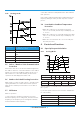


No. Name CN# Meaning
1 Power Supply
CN1 L1_in: connect to L1-line (230V AC input)
CN3 L2_in: connect to L2-line (230V AC input)
2 TP CN8 Exhaust temp. sensor TP
3 TESTPORT CN35 used for testing
4 HEAT1 CN19/CN20 connect to chassis heater, 208-230V AC when is ON
5 HEAT2 CN24/CN25 connect to compressor heater, 208-230V AC when is ON
6 4-WAY CN17/CN18 connect to 4 way valve, 208-230V AC when is ON.
7 AC-FAN2 CN31/CN36/CN28 connect to AC fan2
8 AC-FAN1 CN27/CN34/CN32 connect to AC fan1
9 H-PRO/L-PRO CN10 connect to low&high pressure switch
10 Compressor Top CN14 connect to compressor top temperature sensor
11 T2B CN11 connect to pipe temp. sensor T2B
12 T4 T3 CN9 connect to pipe temp. sensor T3, ambient temp. sensor T4
13 PMV
CN15/CN23/CN26/
CN30/CN33/CN38
connect to Electric Expansion Valve(A~F)
14 / CN6 connect to IPM&PFC board CN9
15 PQE CN22 Communication to indoor unit