
Lacey Act Declaration Form
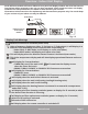

NOTE ON INSTALLATION OF A DIY MULTI-ZONE SYSTEM
Please read this instruction manual fully before you attempt to
install this system. Because there are multiple units, pipes, and
lines to be installed in different locations, and heating/cooling
zones to consider, planning your installation is necessary in order
to help prevent any potential problems. Taking proper
measurements is also vital to determine the line set lengths
needed to connect the indoor units to the outdoor unit. If you find
the standard line set length is not sufficient for your application,
you may need to purchase additional line sets and coupler kits. It
should be noted that it is easier to install the air handlers to the
outer walls. If they are to be mounted to interior walls, line sets
will need to be run to a central location, such as an attic,
basement, or crawlspace, and have them exit the house (to the
outdoor unit) from that location.
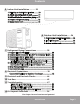
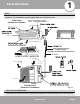
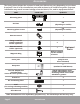
Indoor unit
1. Panel frame
2. Rear air intake grill
3. Front panel
4. Air purifying filter & Air filter (behind)
5. Horizontal louver
6. LCD display window
7. Vertical louver
8. Manual control button (behind front panel)
9. Remote controller holder
Outdoor unit
10. Drain hose, refrigerant connecting pipe
11. MC cable
12. Stop Valve
13. Fan hood
Page 7
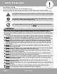
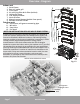
Overview - Diagram
mrcool.com
Air Inlet
Air Inlet
Air Outlet
Outdoor
Unit
Refrigerant
Piping & Lines
Indoor Units within their zones
13
Fig. 1.2
One-five
One-four
One-three
One-two