Installation & Owner’s Manual PRODIRECT™ SERIES Air Handler HAH140*C Due to updates and constantly improving performance, the information and instructions within this manual are subject to change without notice. Please visit www.mrcool.com/documentation to ensure you have the latest version of this manual. Version Date: 2-22-21 Thank you for choosing MRCOOL. Please read this manual carefully before installation and keep it for future reference.
INDOOR UNIT These instructions are intended as an aid for qualified, licensed service personnel for proper installation, adjustment, and operation of this unit. Read these instructions thoroughly before attempting installation or operation. Failure to follow these instructions may result in improper installation, adjustment, service or maintenance possibly resulting in fire, electrical shock, property damage, personal injury or death. mrcool.
INDOOR UNIT INSTALLATION AND OWNER’S MANUAL INDOOR SPLIT-SYSTEM UNIT MODELS: UP TO 18 SEER 1.
INDOOR UNIT This document is customer property and needs to remain with this unit. These instructions do not cover all of the different variations between systems, nor does it provide for every possible contingency that can arise during installation. All phases of this installation must comply with NATIONAL, STATE, AND LOCAL CODES. This manual could change without expressed written notice. Visit mrcool.com/documentation for the latest versions. 1 SAFETY This is a safety alert symbol.
INDOOR UNIT The unit must be properly and permanently grounded. Failure to do so could result in electrical shock causing personal injury or death. PROPOSITION 65: This appliance contains fiberglass insulation. All manufacturer products meet current federal OSHA Guidelines for safety. California Proposition 65 warnings are required for certain products, which are not covered by the OSHA standards.
INDOOR UNIT The first 3 feet (36 inches) of the supply air plenum and ductwork must be constructed of sheet metal as required by NFPA 90B. The supply air plenum or duct must also have a solid sheet metal bottom directly under the unit with no openings, registers or flexible air ducts located in it. If flexible supply air ducts are used, they can only be located in the vertical walls of the rectangular plenum and must be a minimum of 6 inches from the solid bottom.
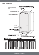
INDOOR UNIT 3 UNIT DIMENSIONS ELECTRICAL CONNECTIONS CAN EXIT THE TOP, OR EITHER SIDE, OF THE UNIT UNIT LENGTH Table 1 mrcool.
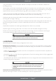
INDOOR UNIT 4 VERTICAL UPFLOW 1) Vertical Upflow configuration is the factory set on all models (see Fig 1) 2) If a side return air opening is required, field fabricate a return air plenum with an opening large enough to supply unit and strong enough to support unit weight. 3) If return air is to be ducted, install duct flush with floor. Use fireproof resilient gasket 1/8 in. to 1/4 in. thick between the ducts, unit, and floor. Set unit on the floor over the opening.
INDOOR UNIT •Using a screwdriver, lift the blue plastic tab with hole away from breaker until breaker releases from mounting opening. •With breaker held in hand, rotate breaker so that the ”on” position is up, and ”off” position is down (with unit in planned vertical mounting position). Insert right wire bundle into top right breaker lug, ensuring all strands of all the wires are inserted fully into lug, and no wire insulation is in the lug. •Tighten lug as tight as possible while holding circuit breaker.
INDOOR UNIT 14SEER AHU Market Model HAH14018 HAH14024 HAH14030 HAH14036 Indoor external static pressure InWC 0.10 0.10 0.15 0.15 Indoor air flow CFM(hi/mi/lo) 723/610/500 938/804/738 1204/1060/919 1376/1235/1161 Indoor external static pressure InWC 0.18 0.18 0.23 0.23 Indoor air flow CFM(hi/mi/lo) 1364/1229/849 1595/1366/1256 2046/1955/1562 2340/2100/1974 Table 2 mrcool.com | Page 8 HAH14042 0.15 1562/1385/1208 0.23 2480/2430/2074 HAH14048 HAH14060 0.20 0.
INDOOR UNIT 7 ELECTRICAL WIRING Field wiring must comply with the National Electric Code and any applicable local ordinance. Disconnect all power to unit before installing or servicing. More than one disconnect switch may be required to de-energize the equipment. Hazardous voltage can cause severe personal injury or death. 8 POWER WIRING It is important that proper electrical power is available for connection to the unit model being installed.
INDOOR UNIT 11 ELECTRICAL DATA Table 3 The air distribution system has the greatest effect on airflow. The duct system is totally controlled by the contractor. For this reason, the contractor should use only industry-recognized procedures. Heat pump systems require a specified airflow. Each ton of cooling requires between 350 and 450 cubic feet of air per minute (CFM), or 400 CFM nominally. Duct design and construction should be carefully done.
INDOOR UNIT 13 EXPANSION VALVE + PISTON INFORMATION The length of warm wire should be≥L2 Balance tube length≥L1 Thermal Expansion Valve (14 SEER Heat Pump) Unit NO.
INDOOR UNIT 14 CONDENSATE DRAIN TUBING DO NOT OVERTIGHTEN DRAIN FITTING TOWARD DRAIN CONNECTION UNIT MUST BE SLIGHTLY INCLINED IMPORTANT 1. When making drain fitting connections to the drain pan, use a thin layer of Teflon paste, silicone, or Teflon tape and install. Hand-tighten the fittings. 2. When making drain fitting connections to drain pan, do not overtighten. Over tightening fittings can split pipe connections on the drain pan. (Continued on next page) mrcool.
INDOOR UNIT • Install drain lines so they do not block service access to front of the unit. A minimum clearance of 2 feet (24 inches) is required for filter, coil or blower removal, and service access. • Make sure unit is level or pitched slightly toward primary drain connection so that water will drain completely from the pan (Refer to Fig. 5) • Use a drain line sized properly to match size of condensate drain pan. • All drain lines must be pitched downward and away from the unit with a minimum of 1/8 in.
INDOOR UNIT 16 FILTER INSTALLATION DIMENSIONS Table 4 AIR FILTER REMOVAL 1. Tear down the two bolts marked A and B, remove the cover for air filter (Refer to Fig. 6). 2. Hold the edge of the air filter and extract out . 3. Clean the air filter. A vacuum cleaner or pure water may be used to clean the air filter. If the dust accumulation is too heavy, use soft a brush and mild detergent to clean it and allow it to dry out in cool place. mrcool.
INDOOR UNIT 17 WIRING DIAGRAMS Thermostat Wiring - 6 Conductor | 18 Guage | Low Voltage Control Wiring for A/C Systems only W1 A C Control Wiring for Heat Pump Systems W1 mrcool.
INDOOR UNIT High Voltage Wiring 1. To avoid the electrical shock, please connect the air conditioner with the ground lug. The main power plug in the air conditioner has been joined with the ground wiring, please do not change it freely. 2. Use a dedicated circuit. 3. Do not pull the power wiring hard. 4. When connecting the air conditioner with the ground, observe the local codes. 5. If necessary, use the power fuse, circuit breaker, or the corresponding scale ampere.
INDOOR UNIT Applicable to 60K of 13-14 SEER Wiring Diagram to Adjust Blower Volume Speed To adjust blower speed, use the diagram below to wire according to the desired speed: CN12 is the air volume output port. The air volume is adjusted by connecting the wires with different speeds for the motor to the port CN12. Regardless of the high, medium or low wind speeds, it is only connected to CN12. Do not adjust CN13. Black = High Red = Medium Blue = Low mrcool.
INDOOR UNIT 18 ELECTRIC WIRING GAUGE NOTE: The cross-section areas of wires or lines should not be less than the corresponding line measurements listed in the table below; Besides, if the power wires from the unit are quite long, please choose the windings with larger cross-section area to guarantee the normal power supply. Table 5 Signal Line Signal Line Table 6 Signal Line Signal Line mrcool.
INDOOR UNIT 19 ELECTRIC HEAT KIT INSTALLATION (OPTIONAL) CAUTION 1. Ensure that all power supply is disconnected prior to installing the heat kit. 2. A means of strain relief and conductor protection must be provided at the supply wire entrance into 3. 4. 5. 6. 7. cabinet. Only use copper conductors. Installation must follow National Electric Code (NEC) and other applicable codes.
INDOOR UNIT 20 TROUBLESHOOTING INDOOR UNIT Display mode Status description Green light always on No system alarm and error, normal standby Red light always on Evaporator temperature sensor (T2) failure Evaporator high and low temperature protection Green light always on & yellow light flashing Green light flashing system is in normal operating status T2 Evaporator temperature sensor failure Evaporator temp.
INDOOR UNIT Evaporator high temperature protection (for heating mode) High temp.
PRODIRECT™ Series The design and specifications of this product and/or manual are subject to change without prior notice. Visit www.mrcool.com for the latest documentation.