Owner & Installation Manual PRODIRECT™ SERIES Split System Heat Pump & Air Conditioner 13 -14 SEER 1.5-5 Tons Model: HHP140* Please read the installation manual carefully before installation and keep for future reference. Please note: The design and specifications of this product and/or manual are subject to change without prior notice. Visit www.mrcool.com for the latest documentation.
OUTDOOR UNIT These instructions are intended as an aid for qualified licensed service personnel for proper installation, adjustment and operation of this unit. Read these instructions thoroughly before attempting installation or operation. Failure to follow these instructions may result in improper installation, adjustment, service or maintenance possibly resulting in fire, electrical shock, property damage, personal injury or death. mrcool.
OUTDOOR UNIT INSTALLATION AND OWNER’S MANUAL OUTDOOR UNIT MODELS Table of Contents 1 DIMENSIONS 2 SERVICE SPACE 3 PIPING DIAGRAMS 4 WIRING DIAGRAMS 5 ELECTRIC CHARACTERISTICS 6 OPERATION LIMITS 7 INSTALLATION PROCEDURE 8 LOCATION SELECTION 9 OUTDOOR UNIT INSTALLATION (TOP DISCHARGE UNIT) 10 REFRIGERANT PIPE INSTALLATION 11 VACUUM DRYING AND LEAKAGE CHECKING 12 ADDITIONAL REFRIGERANT CHARGE 13 ENGINEERING OF INSULATION 14 ENGINEERING OF ELECTRICAL WIRING 15 TEST OPERATION 16 TROUBLESHOOTING mrcool.
OUTDOOR UNIT 1. Dimensions Fig. 1 21-3/4 [554] 21-3/4 [554] 21-3/4 [554] 21-3/4 [554] 21-3/4 [554] 21-3/4 [554] Table - 1 mrcool.
OUTDOOR UNIT 2. Service Space Fig. 2 mrcool.
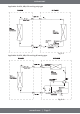
OUTDOOR UNIT 3. Piping Diagrams Applicable for 18k, 24k, 30k, 36k cooling only type Fig. 3-1 Applicable for 18k, 24k, 30k, 36k cooling & heating type Fig. 3-2 mrcool.
OUTDOOR UNIT Applicable for 42k, 48k, 60k cooling only type Fig. 3-3 Applicable for 42k, 48k, 60k cooling & heating type Fig. 3-4 mrcool.
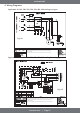
OUTDOOR UNIT 4. Wiring Diagrams Applicable for 18k, 24k, 30k, 36k, 42k, 48k, 60k cooling only type Fig. 4-1 1. Grounded and all wiring to conform to I.E.C. 2. Replacement wire must be the same gauge and insulation type as original wire. 3. The units should install the stated-cross-section ground wire and keep it grounding reliably. 4.According to the actual connection of low-voltage switch or short wiring. Applicable for 18k, 24k, 30k, 36k, 42k, 48k, 60k cooling & heating type Fig. 4-2 1.
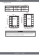
OUTDOOR UNIT 5. Electric Characteristics Table - 2 mrcool.
OUTDOOR UNIT 6. Operation Limits Table - 3 Range of Operation Range of Operation Fig. 6 When the ambient temperature is more than 109°, the restart time may take 15-20 minutes. It is suggested to install a booster in the outdoor unit (18K, 24K, 30K, and 36K units only) to shorten the restart time. In the case of high and low pressure imbalance, a booster can increase the starting torque of the compressor allowing it to start normally. mrcool.
OUTDOOR UNIT 7.
OUTDOOR UNIT 8. Location Selection 8.1 Indoor unit location selection • The place should easily support the indoor unit's weight. • The place is easily accessible for indoor unit installation and inspection. • The place can accommodate horizontal indoor unit installation. • The place allows easy water drainage. • The place can easily connect with the outdoor unit. • The place offers sufficient air circulation in the room. • There should not be any heat source or steam near the unit.
OUTDOOR UNIT 9. Outdoor Unit Installation (Top Discharge Unit) Location selection Before starting the installation, find and select a suitable location for both the indoor and outdoor unit using the guidelines listed previously. Observe all limitations and clearance requirements. The outdoor unit must have sufficient clearance for air entrance to the condenser coil, for air discharge, and for service access. Fig 9-1 Note: For multiple unit installations, units must be spaced a minimum of 18 inches apart.
OUTDOOR UNIT Warning: The outdoor unit should not be installed in an area where excessive mud or ice could cause personal injury. Elevate the unit sufficiently to prevent any blockage to the air entrances from excessive snow or precipitation. Check the local weather bureau for average snow accumulation in the area. Be sure to Isolate the unit from rain gutters to avoid any possible foundation wash out.
OUTDOOR UNIT 10. Refrigerant Pipe Installation Maximum pipe length and height drop Consider the allowable pipe length and height drop when deciding the installation position. Make sure the distance and height drop between the indoor and outdoor units do not exceed the data in the following table. Ft. (M) Ft. (M) The procedure of connecting pipes Table - 4 1. Choose the pipe size according to Table 4 above. 2. Confirm the cross way of the pipes. 3. Measure the necessary pipe length. 4.
OUTDOOR UNIT • Precautions should be taken to prevent heat damage to service valve by wrapping a wet rag around it, as shown in the image below. Also, protect all painted surfaces and insulation during brazing. After brazing, cool joint with a wet rag. •Valve can be opened by removing the plunger cap, and then fully insert a hex wrench into the stem turning counter-clockwise until the valve stem just touches the chamfered retaining wall. Fig. 10-2 mrcool.
OUTDOOR UNIT 11. Vacuum Drying and Leakage Checking Purpose of vacuum drying • Eliminating moisture in system to prevent the phenomena of ice-blockage and copper oxidation Ice-blockage can cause abnormal operation of system, while copper oxide can damage the compressor. • Eliminating the non-condensable gas (air) in the system to prevent the components from oxidizing, pressure fluctuation, or bad heat exchange during the operation of system.
OUTDOOR UNIT 12. Additional Refrigerant Charge After the vacuum drying process is carried out, the additional refrigerant charge process needs to be performed. The outdoor unit is factory charged with refrigerant. The additional refrigerant charge volume is decided by the diameter and length of the liquid pipe between the indoor and outdoor unit. Refer to the following formula to calculate the charge volume. V: Additional refrigerantcharge volume (oz). L : The length of the liquid pipe (ft).
OUTDOOR UNIT 13. Engineering of Insulation Insulation of refrigerant pipe Operational procedure of refrigerant pipe insulation 1. Cut the suitable pipe 2. Insulation (except joint section) 3. Flare the pipe 4. Piping layout and connection 5. Vacuum drying 6. Insulate the joint parts Purpose of refrigerant pipe insulation • During operation, temperature of gas pipe and liquid pipe could be extremely hot or cold.
OUTDOOR UNIT Insulation material selection for drainage pipe • The insulation material should be a flame retardant material, and the material should be in accordance to the guidelines of local law. • Thickness of insulation layer is usually above 10mm. • Use specific glue to paste the seam of insulation material, and then bind with adhesive tape. The width of tape should not be less than 5cm. Make sure it is firm and avoid condensation.
OUTDOOR UNIT Table - 7 mrcool.
OUTDOOR UNIT 15. Test Operation The test operation must be carried out after the entire installation has been completed.
OUTDOOR UNIT 16. Troubleshooting System Alarm: Green light or Yellow light slowly flashes System lock: Green light goes out and Yellow light is on Turn off power for 10-15 minutes and then restart. mrcool.
OUTDOOR UNIT T3 Condenser Temperature sensor fault Condenser temp. sensor abnormal Check the connection between sensor and PCB Error Well connected, then replace the sensor or PCB No Sensor is open circuit? Check the sensor is good or not? Sensor is short circuit? Error Replace the bad sensor No Error Component damaged? Check PCB Replace PCB Wet? T5 discharge Temperature sensor fault Discharge temp.
OUTDOOR UNIT Low pressure alarm Low Pressure alarm Error Lack of refrigerant Repair the leakage & charge refrigerant OK Error Check the gas side of the system Remove the dirty and open the valve OK Error Heat exchanger is in poor condition Repair the heat exchanger OK Error Check the PCB and pressure swich Replace PCB or switch High pressure alarm High Pressure alarm Error Check and repair one by one Heat exchanger of outdoor is bad OK Error Check the liquid side of the system OK Remove
OUTDOOR UNIT (T3)High temperature protection High temp.
PRODIRECT™ Series The design and specifications of this product and/or manual are subject to change without prior notice. Consult with the sales agency or manufacturer for details.