Installation Manual For General Installation. Model-specific manuals will be included with multi-zone condensers or as applicable. Olympus Series Single (Hyper Heat & Energy Star) & Multi-Zone Models For more details visit www.MrCool.
CONTENTS PRECAUTIONS 2 2 9K & 12K INSTALLATION 3 4 4 5 8 18K & 24K INSTALLATION 9 11 14 1 For more details visit www.MrCool.
PRECAUTIONS Installation Precautions Safety Precautions WARNING CAUTION WARNING CAUTION 2 For more details visit www.MrCool.
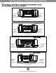
9K & 12K Installation - INSTALLATION LOCATION Indoor Unit Outdoor Unit 15 cm / 5.9 in or more 12cm / 4.7 in o r Required more 2.0 m / 6.5 ft or more For Ceilings Greater Than 9 Foot Suggested Floor Clearance is 230cm(90.55in) For Ceilings Less Than 9 Foot Suggested Floor Clearance is Suggested cm / 4.7 in o rm ore 60 cm / 23.6 in or more 200cm(78.55in) 12 30 c m /1 1.8 in or 1.8 m /1 30 c more 6 / 6. 2m ft or e mor 60 c m/ 3 For more details visit www.MrCool.com 23.
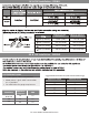
9K & 12K Installation - ACCESSORIES 6 Smart Controller Kit (1) (w/ Manual) 7 8 Neoprene (1) (Sealant for Wall Sleeve) 9K & 12K Installation - OUTDOOR MOUNTING DIMENSIONS NOTE: Outdoor unit dimension in/mm (WxHxD) Mounting dimensions A(in/mm) B(in/mm) 4 For more details visit www.MrCool.
9K & 12K Installation - INDOOR MOUNTING DIMENSIONS NOTE: 11 Right rear side refrigerant pipe hole Left rear side refrigerant pipe hole 2.6in/65mm 2.6in/65mm Series 9K Models 11 Right rear side refrigerant pipe hole Left rear side refrigerant pipe hole 2.6in/65mm 2.6in/65mm Series 12K Models Left rear side refrigerant pipe hole 1.8in/45mm 2.6in/65mm Right rear side refrigerant pipe hole 2.6in/65mm Series 18K Models Left rear side refrigerant pipe hole 2.
9K & 12K Installation - PIPING 1/4in/6.35mm 3/8in/9.52mm ) ) ) s) ) ) ) ) ) Tightening torque (lbf.in/N.cm) ) Additional tightening torque(lbf.in/N.cm) 1/4in (6.35mm) 132.8 (1500) 141.59 (1600) 3/8in (9.52mm) 221.34 (2500) 230.02 (2600) 1/2in (12.7mm) 309.73 (3500) 318.56 (3600) 5/8in (15.88mm) 398.23 (4500) 415.
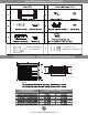
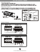
9K & 12K Installation - WIRING Indoor Wire Connection Outdoor Wire Connection G Connection Diagrams 115V~ models L N S G 1(L ) 2(N ) S L N Power supply 208-230V~ models L1 L2 S G L1 L2 S L1 L2 Power supply 7 For more details visit www.MrCool.
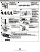
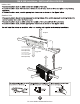
K & 12K Installation - INSTALLATION PROCESS 2 1 ) (0.2~0.3inch) a 4 3 5 6 7 8 9 NOTE: NOTE: Using manual operation 8 For more details visit www.MrCool.
18K 9K &&12K 24KInstallation Installation- -INSTALLATION INSTALLATIONLOCATION LOCATION Indoor Unit Outdoor Unit 15 cm / 5.9 in or more 12cm / 4.7 in o r Required more 2.0 m / 6.5 ft or more For Ceilings Greater Than 9 Foot Suggested Floor Clearance is 230cm(90.55in) For Ceilings Less Than 9 Foot Suggested Floor Clearance is Suggested cm / 4.7 in o rm ore 60 cm / 23.6 in or more 200cm(78.55in) 12 30 c m /1 1.8 in or 1.8 m /1 30 c more 6 / 6. 2m ft or e mor 60 c m/ 23.
18K & 24K Installation - INSTALLATION LOCATION Step 3: Anchor outdoor unit The outdoor unit can be anchored to the ground or to a wall-mounted bracket witha bolt and nut 10 or 8.z. H UNIT MOUNTING DIMENSIONS sizes and the distance between their mounting feet. Prepare the installation base of the unit according to the dimensions below. W D A Air Inlet Air Inlet B Fig. 4.5 Air Outlet Outdoor Unit Dimensions (inches) Mounting Dimensions (inches) Width (A) Depth (B) O-HH-09-HP-C-230 31.50 x 21.
18K & 24K Installation - INDOOR INSTALLATION vibration. 11in NOTE: Left rear side refrigerant pipe hole Mounting Indoor Unit Right rear side refrigerant pipe hole 2.6in 11in Series 9K Models Series 12K Models NOTE: Mount the Installation Plate and drill holes in the wall according to the wall structure 39in Series 18K Models unless otherwise stated.) Correct orientation of Installation Plate 46.7in Series 24K Models Dill a Hole in the Wall 11 For more details visit www.MrCool.
18K & 24K Installation - INDOOR INSTALLATION USE THE RIGHT CABLE Suggested Minimum Wire Size (AWG: American Wire Gage): • Outdoor power cable is not provided • Indoor power / signal cable from outdoor unit is provided • See table below for gauge requirements Model Series Appliance Amps (A) Appliance Amps AWG Wire Size 10 13 18 25 30 18 16 14 12 10 AWG 9K & 12K 15 14 18K 20 12 24K 25 10 Indoor Wire Connection Outdoor Wire Connection G 208-230V~ models L1 L2 S G L1 L2 S L1 L2
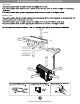
18K & 24K Installation - INDOOR INSTALLATION Step 4: Prepare refrigerant piping The refrigerant piping is inside an insulating sleeve attached to the back of the unit. You must prepare the piping before passing it through the hole in the wall. Connect the indoor unit first, then the outdoor. If existing connective piping is already embedded in the wall, proceed directly to the Connect Drain Hose step.
Indoor Unit- Installation 18K & 24K Installation INDOOR INSTALLATION Step 5: Connect drain hose By default, the drain hose is attached to the left-hand side of unit (when you’re facing the back of the unit). However, it can also be attached to the right-hand side. Make there are no kinks or dent in the hose to ensure proper drainage. 1. To ensure proper drainage, attach the drain hose on the same side that your refrigerant piping exits the unit. 2.
18K & 24K Installation - INDOOR INSTALLATION Indoor Unit Installation 18K & 24K Installation - OUTDOOR INSTALLATION Incorrect Correct Barrier Strong wind Strong wind Drain Joint Installation NOTE: Seal Drain joint (A) 15 For more details visit www.MrCool.
18K & 24K Installation - OUTDOOR INSTALLATION Connecting Refrigerant Piping Flaring 90O "A" Bar A(mm) Outer diam. (mm) Max. Min. 6.35 1.3 0.7 9.52 1.6 1.0 12.7 16 1.8 2.2 1.0 2.0 Copper pipe Indoor unit tubing Outer diam. Tightening Connections 6.35mm 9.52mm 12.7mm 16mm Handle Bar Clamp handle Flare nut Pipings Tightening Additional tightening torque(N.cm) torque(N.cm) 1500 (153kgf.cm) 2500 (255kgf.cm) 1600 (163kgf.cm) 3500 (357kgf.cm) 4500 (459kgf.cm) 3600 (367kgf.
K & 24K Installation - OUTDOOR INSTALLATION NOTE: is tested basing on the pipe length of 24.6 feet. Air Purging Connective pipe length Air purging method Less than 7.5m Use vacuum pump More than 7.5m Use vacuum pump Additional amount of refrigerant to be charged Liquid side: 6.35mm Liquid side: 9.52mm: R22: (Pipe length-7.5)x30g/m R22: (Pipe length-7.5)x60g/m R410A: (Pipe length-7.5)x15g/m R410A: (Pipe length-7.5)x30g/m CAUTION Outdoor unit A a spanner wrench.
18K & 24K Installation - OUTDOOR INSTALLATION Leak Check Indoor unit chec k point D C B A C over Outdoor unit chec k point CAUTION A: Lo packed valve B: Hi packed valve C and D are ends of indoor unit connection. Test Run AUTO/COOL Manual control button Manual control button 18 For more details visit www.MrCool.
Olympus Series Single (Hyper Heat & Energy Star) & Multi-Zone Models For more details visit www.MrCool.