
Installation Manual

Page 4 of 9 507043-04Cmrcool.com
If ANY refrigerant tubing is required to be buried by state
or local codes, provide a 6 inch vertical rise at service
valve.
CAUTION
Before making braze connections, be sure all joints are
clean. Before heat is applied for brazing, dry nitrogen
and scale formation on the inside of the tubing.
The following is the recommended method for making
braze connections at the refrigerant line connections:
9. Debur and clean refrigerant tube end with emery cloth
or steel brush.
10.
11. Wrap wet rags over valves to protect from heat.
12.
13. Braze joint, using a suitable brazing alloy for copper to
copper joints.
14. Quench the joint and tubing with water using a wet
help cool area.
Leak Check
Refrigeration lines and indoor coil must be checked for leaks
after brazing and before evacuation. The recommended
procedure is to apply a trace amount of vapor refrigerant
(approximately two ounces or 3 psig) into the line set and
indoor coil, then pressurize with 150 psig of dry nitrogen.
Use a refrigerant leak detector to check all joints. The
system may also be checked for leaks using a halide torch
or pressure and soapy solution. After completion of leak
check, relieve all pressure from system before evacuation.
Evacuating and Charging Instructions
It is unlawful to release refrigerants into the atmosphere.
WARNING
These outdoor units are pre-charged at the factory with
adequate refrigerant to handle 15 feet of refrigerant tubing.
1. Connect the vacuum pump to the center hose of the
manifold gauge set, the low-pressure manifold gauge
to the vapor service valve and the high pressure
manifold gauge to the liquid service valve.
2. The valves should be kept in the “front seated” (closed)
position. This will allow evacuation of the refrigeration
lines and the indoor coil, without disturbing the factory
charge in the outdoor unit.
3. Follow the vacuum pump manufacturer’s instructions.
Allow the pump to operate until the system has been
evacuated down to 300 microns. Allow the pump to
continue running for an additional 15 minutes. Turn
OFF the pump and leave the connections secured
to the two (2) service valves. After 5 minutes, if the
system fails to hold 1000 microns or less, check all
procedure.
4. Isolate the vacuum pump from the system by closing
the shutoff valves on the gauge-set. Disconnect the
vacuum pump.
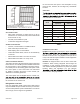
5. After evacuation of the connecting lines, remove the
service valve cap and fully insert the hex wrench into the
stem. A back-up wrench is required on the valve body
to open the valve stem. Back-out counterclockwise
until the valve stem just touches the coined edge.
Replace service valve cap and torque to 8-11 ft-lb on 3/8”
valves; 12-15 ft-lb on 3/4” valves; 15-20 ft-lb on 7/8” valves.
Electrical Connections
ELECTRICAL SHOCK HAZARD!
Turn OFF electric power before connecting
unit, performing any maintenance or
removing panels or doors. More than one
disconnect may be required to turn off all
power.
FAILURE TO DO SO COULD RESULT
IN BODILY INJURY OR DEATH.
WARNING
Be sure to check all local codes to determine that the unit
is installed in accordance with local requirements. Consult
the National Electric Code for wire size requirements. Use
60° C or higher copper wires only. Always provide ground
connections to the outdoor unit. Power supply must agree
with the rating on the unit nameplate.
Provide line voltage power supply to unit from a properly
sized disconnect switch. Route power and ground wires
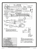
from disconnect switch to unit. Line voltage connections
are made at the line side of the contactor in the control box
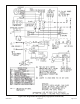
of the outdoor unit. Follow the wiring diagram attached to
inside of the access panel.
Proper circuit protection recommendations are indicated
on Unit Rating Plate. Time delay fuses are required to
prevent blowing due to starting current (the current in rush
when equipment starts is reffered to as the Locked Rotor
Amps or LRA).