The Signature Series is NOT designed for amateur installation. Installation SHOULD be performed by an authorized technician. Please read this manual carefully before installation and keep it for future reference. Owner & Installation Manual Signature Series MAHM*CTA AIR Handler The Signature Series is NOT designed for amateur installation. Installation SHOULD be performed by an authorized technician. Please read this manual carefully before installation and keep it for future reference.
INSTALLATION INSTRUCTIONS MAHM*CTA Series Air Handler This manual must be left with the homeowner for future reference. This is a safety alert symbol and should never be ignored. When you see this symbol on labels or in manuals, be alert to the potential for personal injury or death. Table of Contents ......2 Shipping and Packing List ...........................................3 General........................................................................3 Requirements .................................
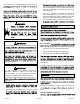
MAHM*CTA 1 (25) DETAIL OF PIPING PLATE 14-1/2 (368) SUPPLY AIR OPENING 1 (25) 4-3/8 (111) LOW VOLTAGE INLETS (Top and Right Side) LINE VOLTAGE INLETS (Top and Left Side) CONDENSATE DRAINS (2) (Upflow and Downflow) 2-3/4 (70) 3-1/2 (89) 1-3/4 (44) TOP VIEW 3/4 (19) CONDENSATE DRAINS (2) (Horizontal) 2-3/8 (60) C 1 (25) 4-3/4 (121) 3/4 (19) SUCTION LINE LIQUID LINE 22 (559) B LINE VOLTAGE INLETS (Top and Right Side) CIRCUIT BREAKER COVER LOW VOLTAGE INLETS (Either Side) AIR FLOW A PIPIN
Shipping and Packing List Requirements Package 1 of 1 contains: Check the air handler for shipping damage; if found, immediately contact the last carrier. Check the unit rating NOTE: Special procedures are required for cleaning the all-aluminum coil in this unit. See Page 20 in this instruction for information. can result in back or other type of injury. MAHM*CTA units include a factory-installed check/ capacities.
Do not remove the cabinet knockouts until it has been • they exit the conduit opening. Sealant is required to prevent air leakage into, and condensate from forming inside of, the air handler, the control box, and on the electrical controls. the installation. conditions. Consider required clearances, space, routing requirements for refrigerant line, condensate disposal, information. • This unit is approved for installation clearance to combustible material as stated on the unit rating plate.
Right-Hand Discharge 1. The air handler must be supported on the bottom only 1. connections. frame. 2. horizontal drain pan. 3. 2. With access door removed, remove drain line plugs to install drain lines. end of the unit and level from front to back of unit (see Figure 6). NOTE: The horizontal drain pan is not required in 4. 3. Place the unit in the desired location and slope unit. Connect return and supply air plenums as required 4.
NOTE: into the coil end plate engaging holes. Misaligned After removal of drain pan plug(s), check drain hole(s) to verify that drain opening is fully open and free of any debris. Also check to make sure that no debris has fallen into the drain pan during installation that may plug up the drain opening. 4. 8. support rail as illustrated. 9. Rotate drain pan 180º front-to-back and install it on the opposite side of the coil.
Sloping The Unit Condensate Drain THIS CORNER SHOULD BE 5/8" (+/- 1/8") HIGHER THAN DRAIN CORNER in the condensate drain lines (primary and auxiliary, through the drain lines into the air supply. NE LA P L VE LE DRAIN CORNER pipe to the outside of the building, is required in all pan. In some localities, local codes may require a secondary drain pan for any horizontal installation. Figure 6.
NOTE: connections. 7. On some pans, the primary and secondary drain holes have knockouts. Route the drain line to the outside or to an appropriate drain. Drain lines must be installed so they do not block service access to the front of the air handler. A 24” and service access. 1. NOTE: MAHM*CTA includes green (main drain) and red (secondary drain) Test Condensate Drain Test the drain pan and drain line after installation: 1.
Brazing Refrigerant Lines and performance may be reduced. The pressure drop may also cause the limit to trip more frequently during Refrigerant lines must be clean, dry, refrigerant-grade copper lines. Air handler coils should be installed resulting in an increase in the number of service combinations. Handle the refrigerant lines gently during the installation against the data given in the appropriate Product restriction. Service and Application Note ACC002 (August 2000).
NOTE: . 1. hazardous to your health. the lines in a direct path, avoiding unnecessary turns and bends. Avoid breathing vapors or fumes from brazing areas. 2. Make sure that the suction line is insulated over the entire exposed length and that neither suction nor 3. To avoid damaging the rubber grommets in the cabinet Wear gloves and protective goggles or face shield to protect against burns. source. NOTE: suction line connections. prevent oxidation and the introduction of moisture into the system.
PLEASE READ IMPORTANT ISSUES CONCERNING BRAZING OPERATIONS IN THE BRAZING REFRIGERANT LINES SECTION BEFORE PROCEEDING. NOTE - REFER TO OUTDOOR UNIT INSTALLATION INSTRUCTIONS FOR REFRIGERANT PIPING SIZE REQUIREMENTS. NOTE - Use silver alloy brazing rods with five or six percent minimum silver alloy for copper-to-copper brazing, 45 percent alloy for copper-to-brass and copper-to-steel brazing.
Sealing the Unit Electric Shock Hazard. Can cause injury or death. Unit must be properly grounded in installed in an unconditioned area. If installed in an unconditioned space, sealant should be pole contactors. Disconnect all remote electric Electric Shock Hazard. sealing strips, caulking, or equivalent sealing method Can cause injury or death. Foil-faced insulation has conductive characteristics similar to metal. Be sure there insulation.
• voltage and line voltage. Refer to the dimension TOP • provided caps to seal holes not used. • installed electric heat) is given in Figure 14. Refer to for proper installation. USE COPPER CONDUCTORS ONLY SIDE 1. 2. Remove the air handler access panel. 3. Figure 12. Control Panel Relocated to End Panel connection box. 4. 208 Volt Conversion 5. 1. Replace the air handler access panel. 2. Remove the air handler access panel. 3.
Figure 14. Typical Wiring Diagram MAHM*CTA Page 14 of 22 mrcool.
Figure 15. Typical Wiring Diagram 507787-01C MAHM*CTA mrcool.
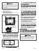
THERMOSTAT AIR HANDLER R THERMOSTAT G SEE NOTE AIR HANDLER R G BU SEE NOTE BU W Y HEAT‐ONLY APPLICATION AIR CONDITIONER UNIT THERMOSTAT AIR HANDLER R COOLING‐ONLY APPLICATION THERMOSTAT AIR HANDLER G R W BK SEE NOTE Y BU CONNECT COMMON WIRE ONLY IF REQUIRED G HEAT PUMP UNIT (REFER TO THE APPROPRIATE THERMOSTAT INSTALLATION INSTRUCTIONS) BK W BU HEAT PUMP APPLICATION WITH ELECTRIC HEAT AIR CONDITIONER UNIT COOLING APPLICATION WITH ELECTRIC HEAT NOTE - Connect common wire only if r
BLOWER RELAY NOTE - Refer to wiring diagram located on the unit ance (table 2). All air data measured external to unit with 1 inch non-pleated air filter in place. All factory settings are medium speed. 5 2 BLOWER RELAY HARNESS PLASTIC CAPS BLUE (MED) RED (L0) BLACK (HI) All data given while air handler is operating with a dry DX coil. YELLOW (COM) All downflow applications run on high speed when utilizing electric heat. 4-PIN BLOWER CONNECTOR Figure 17.
Check-Out Procedures 1. Set thermostat to call for auxiliary heat (approximately NOTE: minimum of 3 minutes for all sequencers to cycle on. instructions. 2. Set the thermostat so that it does not call for heat. Pre-Start-Up Checks • Is the air handler properly and securely installed? Operation • Time Delay Relay • Will the unit be accessible for servicing? • Has an auxiliary pan been provided under the unit could cause damage? 1.
When the thermostat calls for heating, 24 volts is applied the circuit to the contactor in the outdoor unit, starting the compressor and outdoor fan motor. If the room temperature continues to decrease, the circuit room thermostat. Circuit R-W1 energizes a heat sequencer. REPLACED before the unit is put back into operation. separated or torn. Matte- or foil-faced insulation is installed in indoor thermostat. They may also be connected to a second heating stage W2 on the thermostat sub-base.
Professional Maintenance Use of Air Handler During Construction It is not recommended to use this air handler unit during any unit. Air handler units may be used for heating (heat pumps) conditions are met: • A room thermostat must control the air handler. The (less than 50psi). If the coil cannot be cleaned using • thoroughly after cleaning. maintained during construction. • completion. (salt). • The air handler evaporator coil, supply fan assembly • according to these installation instructions.
Installing Contractor’s Name_______________________ Installing Contractor’s Phone_______________________ Job Address____________________________________ Installing Date_______________________________ Air Handler Model #___________________________ Thermostat 9 SUPPLY AIR Disconnect Switch Line Voltage 3 8 2 Integrated Control Temperature 1 Duct System 6 Blower Motor Amps 7 Electric Heat Amps 5 Duct Static RETURN AIR 1 Filter DUCT SYSTEM 5 Sealed Insulated (if necessary) Registers Open and Unob
Installing Contractor’s Name_______________________ Installing Contractor’s Phone_______________________ Job Address____________________________________ 1 Duct System Thermostat 2 Integrated Filter Installing Date_______________________________ Air Handler Model #___________________________ Disconnect Switch 9 Control Line Voltage 3 1 Duct System RETURN AIR SUPPLY AIR 6 Electric Heat Amps 4 Drain Line 7 Blower motor Amps 5 8 Duct Static 1 Temperature DUCT SYSTEM 5 dry coil SUPPLY AIR
Signature Series MAHM*CTA Air Handler ELECTRICIAN and/or HVAC TECHNICIAN: LICENSE #: INSTALLATION DATE: INSTALLATION LOCATION: SERIAL NUMBER: The design and specifications of this product and/or manual are subject to change without prior notice. Consult with the sales agency or manufacturer for details.