
Instructions / Assembly


507787-01Cmrcool.comPage 22 of 22
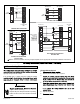
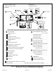
RETURN
AIR
SUPPLY
AIR
2
Duct Static
5
Line Voltage
3
4
Drain Line
ELECTRIC HEAT AMPS____________
8
8
7
5
Filter
Blower motor Amps
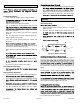
DUCT SYSTEM
SUPPLY AIR DUCT
Sealed
Insulated (if necessary)
Registers Open and Unobstructed
RETURN AIR DUCT
Sealed
Filter Installed and Clean
Registers Open and Unobstructed
INTEGRATED CONTROL
Jumpers Configured Correctly (if applicable)
Appropriate Links in Place (if applicable)
VOLTAGE CHECK
Supply Voltage ___________
Electrial Connections Tight
1
2
3
DRAIN LINE
Leak Free
4
TOTAL EXTERNAL STATIC (dry coil)
Supply External Static ______ ______
TEMPERATURE DROP (Cooling Mode)
Return Duct Temperature ___________
THERMOSTAT
Adjusted and Programmed
Return External Static ______ ______
Total External Static = ______ ______
6
6
Supply Duct Temperature − ___________
Temperature Drop = ___________
TEMPERATURE RISE (Heating Mode)
Return Duct Temperature __________
Supply Duct Temperature − __________
Temperature Rise = __________
Operation Explained to Owner
9
Electric Heat Amps
7
Explained Operation of System to Homeowner
Technician’s Name:_______________________Date Start−Up & Performance Check Completed__________
Installing Contractor’s Name_______________________
Installing Contractor’s Phone_______________________
Job Address____________________________________
Installing Date_______________________________
Air Handler Model #__________________________
_
Thermostat
9
1
1
8
INDOOR BLOWER AMPS___________
Temperature
Duct System
Duct System
Integrated
Control
Disconnect
Switch
INDOOR BLOWER CFM____________
Low Voltage _____________
dry coil wet coil
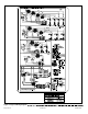
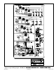
Figure 21.