The Signature Series is NOT designed for amateur installation. Installation SHOULD be performed by an authorized technician. Please read this manual carefully before installation and keep it for future reference. Owner & Installation Manual Signature Series MGM*95SE*XA Gas Furnace The Signature Series is NOT designed for amateur installation. Installation SHOULD be performed by an authorized technician. Please read this manual carefully before installation and keep it for future reference.
INSTALLATION INSTRUCTIONS MGM*95SE*XA Warm Air Gas Furnace This manual must be left with the homeowner for future reference. Table of Contents 2 3 Gas Piping 38 Gas Furnace 6 6 9 13 13 16 50 52 55 56 WARNING CAUTION *F507276-C* MRCOOL, LLC (P) 507276-05C Save these instructions for future reference 507276-05C mrcool.
Unit Dimensions 1 NOTE - C*5 5 R Air B 2 FRONT VIEW SIDE VIEW A Model in. B mm in. C mm 135-5 Page 2 of 57 mm in. mm 16 070-3 110-5 in. D 21 533 505 622 238 23 mrcool.
Parts Arrangement Figure 1. 507276-05C mrcool.
Gas Furnace Shipping and Packing List MG*95SE*XA MG*95SE*XA NOTE: In Direct Vent installations, combustion air is taken Non-Direct Vent installations, combustion air is taken from NOTE: Safety Information DANGER DANGER OF EXPLOSION! Figure 2. MG*95SE*XA Building Codes Figure 3. mrcool.
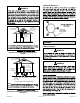
Installation Locations NOTE: Figure 4. Heating Unit Installed Parallel to Air Handler Unit NOTE: NOTE: Installed in Combination with a Cooling Coil Use of Furnace as a Construction Heater DO NOT USE THE UNIT FOR CONSTRUCTION HEAT UNLESS ALL OF THE FOLLOWING CRITERIA ARE MET: 507276-05C mrcool.
• • NOTE: • • • CAUTION COMPONENT FAILURE AS A RESULT OF FAILURE TO Combustion, Dilution & Ventilation Air NOTE: In Non-Direct Vent Installations, combustion air is General • • • Page 6 of 57 mrcool.
WARNING • • • • • • • • • • • • • CAUTION Air from Inside 507276-05C mrcool.
Figure 5. Inside Air from Outside Figure 7. Outside (All Air through Ventilated Attic) ROOF TERMINATED EXHAUST PIPE OUTLET AIR SIDE WALL TERMINATED EXHAUST PIPE (ALTERNATE LOCATION) Page 8 of 57 INLET AIR NOTE−Each air duct opening shall have a free area of at least one square inch per 2,000 Btu (645mm 2 per .59kW) per hour of the total input rating of all equipment in the enclosure.
Shipping Bolt Removal WARNING Ventilation Louvers Inlet Air (Minimum 12 in. (305mm) above Attic Floor) Roof Terminated Exhaust Pipe *Intake Debris Screen (Provided) Figure 11. Furnace Installation * See Maximum Vent Lengths table NOTE Setting Equipment WARNING Figure 9. (Inlet Air from Ventilated Attic and Outlet Air to Outside) Roof Terminated Exhaust Pipe WARNING Ventilation Furnace Louvers (Crawl Space) Coupling or 3 in. to 2 in. Transition (Field Provided) Inlet Air Minimum 12 in.
Figure 12. Setting Equipment Top WARNING Left Side Right Side Bottom (Floor) Top/Plenum 1 in. (25 mm) *Front 00 Back 00 Sides 0† Vent 0 Floor 0† 0 0‡ 0‡ *Front clearance in alcove installation must be 24 in. (610 mm). Maintain a minimum of 24 in. (610 mm) for front service access. †Allow proper clearances to accommodate condensate trap. ‡For installations on a combustible oor, do not install the furnace directly on carpeting, tile or other combustible materials other than wood ooring.
Return Air Guidelines Figure 14. Side Return Air (with Transition and Filter) Figure 15. Optional Return Air Base 507276-05C mrcool.
Right−Hand Discharge L e ft E n d R ight E nd Air Flow Air Flow Bottom (Floor)** Left−Hand Discharge Top L e ft E n d R ight E nd Air Flow Air Flow Bottom (Floor)** Figure 16. Removing the Bottom Panel Removing the Bottom Panel Top 0 Front* 0 Back 0 Ends 0 Vent 00‡ Floor 0‡ 0 0 0† 0 * Front clearance in alcove installation must be 24 in. (610 mm). Maintain a minimum of 24 in. (610 mm) for front service access.
NOTE: Filters NOTE: Furnace Cabinet Width Filter Size Side Return Bottom Return Platform Installation of Horizontal Unit Table 1. Duct System NOTE: Supply Air Plenum Return Air Plenum NOTE: Figure 20. Return Air - Horizontal Applications 507276-05C mrcool.
F891 CAUTION F628 (Pipe) PRIMER & SOLVENT CEMENT IMPORTANT ASTM SPECIFICATION F656 MGM95*E CANADA PIPE & FITTING & SOLVENT CEMENT MARKING ULCS636 POLYPROPYLENE VENTING SYSTEM ULC-S636 ULC-S636 Canadian Applications Only TM ULC-S636 Table 2. mrcool.
STANDARD Capacity VENT PIPE DIA. (in.) Outdoor Outdoor Exhaust Exhaust Accelerator Accelerator (Dia. X Length) (Dia. X Length) CONCENTRIC Flush Mount Kit Concentric Kit Kit Kit 71M80 OR +44W92++ 69M29 OR +44W92++ 60L46 OR 44W93+ 51W11** 2 3 2 070 3 2 090 3 2 110 3 135 3 Table 3. Outdoor Termination Kits Usage Joint Cementing Procedure NOTE: NOTE: DANGER DANGER OF EXPLOSION! 507276-05C mrcool.
NOTE: WARNING CARBON MONOXIDE POISONING HAZARD Venting Practices Figure 21. Removal of the Furnace from Common Vent Page 16 of 57 mrcool.
Vent Piping Guidelines REPLACING FURNACE THAT CHIMNEY OR GAS VENT (Check sizing for remaining appliance) FURNACE (Removed from from common vent system) WAS PART OF A COMMON VENT SYSTEM NOTE: In non-Direct Vent installations, combustion air is In Direct Vent installations, combustion air is taken from WATER HEATER OPENINGS (To Adjacent Room) If this gas furnace replaces a furnace which was commonly vented with another gas appliance, the size of the existing vent pipe for that gas appliance must be check
IMPORTANT Capacity 1 Furnace capacity? 045, 070, 090, 110, 135 2 Which termination? Standard or Concentric? See Table 3 3 Which needs most elbows? Intake or Exhaust? 4 How many? 5 Desired pipe size? 6 What is the altitude? 7 Use Table 5 to find max pipe length. Min. Vent Length* 135 ** Table 4. 2”, 2-1/2” or 3” Figure 24. Page 18 of 57 mrcool.
MG*M95SE*XA Maximum Allowable Intake or Exhaust Vent Length in Feet Number of 90° Elbows Used Capacity 045 070 090 110 Capacity 135 045 070 090 110 39 19 1 25 20 76 61 2 3 20 15 10 15 10 71 66 61 56 51 56 51 5 6 7 8 9 10 Number of 90° Elbows Used 1 2 3 5 6 7 8 9 10 36 31 070 25 20 15 10 20 15 10 090 110 29 135 9 19 36 31 26 21 16 Capacity 045 Capacity 9 045 070 045 070 090 76 71 66 61 56 51 61 56 51 39 36 31 135 045 110 135 29 9 070 090 110 135 109 110
MG*M95SE*XA Maximum Allowable Intake or Exhaust Vent Length in Feet Number of 90° Elbows Used Capacity 045 070 090 110 Capacity 135 045 070 53 1 25 20 68 2 3 20 15 10 15 10 63 58 53 5 6 7 8 9 10 Number of 90° Elbows Used 38 33 28 23 38 33 28 23 18 13 8 Capacity 045 070 25 20 15 10 20 15 10 1 2 3 5 6 7 8 9 10 090 110 090 Capacity 110 135 045 070 090 59 37 17 100 85 32 27 22 17 12 7 12 7 95 90 85 80 75 70 65 60 55 80 75 70 65 60 55 50 045 070 090 68 63 58 53 53 3
Maximum Allowable Exhaust Vent Lengths with Furnace Installed in a Closet or Basement Using Ventilated Attic or Crawl Space for Intake Air in Feet Number of 90° Elbows Used Capacity 045 070 090 110 Capacity 135 045 070 090 110 51 29 9 1 25 20 66 2 3 20 15 10 15 10 61 56 51 5 6 7 8 9 10 Number of 90° Elbows Used 1 2 3 5 6 7 8 9 10 36 31 26 21 070 25 20 15 10 20 15 10 090 110 135 19 36 31 26 21 16 11 6 Capacity 045 Capacity 9 045 070 045 070 090 66 61 56 51 51 29 36 3
Figure 25. Figure 26. Page 22 of 57 mrcool.
Figure 27. Figure 28. Intake Piping 507276-05C mrcool.
CAUTION Figure 29. Ventilation Louvers Inlet Air (Minimum 12 in. (305mm) above Attic Floor) Roof Terminated Exhaust Pipe *Intake Debris Screen (Provided) Furnace * See Maximum Vent Lengths table NOTE: Figure 30. Figure 31. (Inlet Air from Ventilated Attic and Outlet Air to Outside) mrcool.
NOTE: Roof Terminated Exhaust Pipe Ventilation Furnace Louvers (Crawl Space) Inlet Air Minimum 12 in. (305mm) above Crawl Space Floor NOTE: Coupling or 3 in. to 2 in. Transition (Field Provided) *Intake Debris Screen Provided * See Maximum Vent Lengths table NOTE: IMPORTANT Figure 32. (Inlet Air from Ventilated Crawl Space and Outlet Air to Outside) General Guidelines for Vent Terminations IMPORTANT For Canadian Installations Only: 507276-05C mrcool.
Maximum Allowable Exhaust Vent Pipe Length (in ft.) without Insulation in Unconditioned Space For Winter Design Winter Design Temperatures1 ºF (ºC) Unit Input Size Vent Pipe Diameter 045 PVC 070 2 18 PP PVC 16 31 090 2 PP PVC 28 50 110 2 PP PVC 30 13 135 2 PP 2 PP 30 56 9 9 18 18 35 35 9 8 18 16 32 29 30 30 8 8 19 19 26 26 12 10 22 19 30 27 5 5 PVC 52 52 30 30 18 18 13 3 7 15 10 22 10 16 16 1 2 Table 6.
VENT TERMINATION CLEARANCES FOR NON-DIRECT VENT INSTALLATIONS IN THE US AND CANADA INSIDE CORNER DETAIL G H A D E B L Fixed Closed Operable F B B C I Fixed Closed Operable M B K J A B AREA WHERE TERMINAL IS NOT PERMITTED AIR SUPPLY INLET VENT TERMINAL US Installations1 A= Clearance above grade, veranda, porch, deck or balcony B= Clearance to window or door that may be opened C= Clearance to permanently closed window D= Vertical clearance to ventilated soffit located above the ter
VENT TERMINATION CLEARANCES FOR DIRECT VENT INSTALLATIONS IN THE USA AND CANADA INSIDE CORNER DETAIL G H A D E B L Fixed Closed Operable F B B C Operable I Fixed Closed M B A K J B AREA WHERE TERMINAL IS NOT PERMITTED AIR SUPPLY INLET VENT TERMINAL US Installations1 A= Clearance above grade, veranda, porch, deck or balcony B= Clearance to window or door that may be opened C= Clearance to permanently closed window D= Vertical clearance to ventilated soffit located above the termina
Details of Intake and Exhaust Piping Terminations for Direct Vent Installations Inches (MM) 3” (76MM) MIN. NOTE: In Direct Vent installations, combustion air is taken SIZE PER EXHAUST PIPE TERMINATION SIZE REDUCTION TABLE UNCONDITIONED ATTIC SPACE 8” (203MM) MIN NOTE: 1/2” (13MM) FOAM INSULATION IN UNCONDITIONED SPACE 12” (305MM) ABOVE AVERAGE SNOW ACCUMULATION 3” (76MM) OR 2” (51MM) PVC PROVIDE SUPPORT FOR INTAKE AND EXHAUST LINES Figure 36.
FIELD FABRICATED WALL TERMINATION NOTE − FIELD−PROVIDED REDUCER MAY BE REQUIRED TO ADAPT LARGER VENT PIPE SIZE TO TERMINATION 2” (51mm) 3” (76mm) Vent Pipe Vent Pipe D D B A B Intake Elbow C1 C2 A STRAIGHT APPPLICATION A− Minimum clearance above grade or average snow accumulation 12” (305 mm) 12” (305 mm) B− Maximum horizontal separation between intake and exhaust 6” (152 mm) 6” (152 mm) C1 -Minimum from end of exhaust to inlet of intake 8” (203 mm) 8” (203 mm) C2 -Minimum from end of ex
Figure 42. Figure 43. Figure 40. 3”-8” (76MM-203MM) STRAIGHT-CUT OR ANGLE-CUT IN DIRECTION OF ROOF SLOPE 8” - 12” (203MM - 305MM) Minimum 12” (305MM) above chimney top plate or average snow accumulation INTAKE PIPE INSULATION (optional) SHOULDER OF FITTINGS PROVIDE SUPPORT OF PIPE ON TOP PLATE SHEET METAL TOP PLATE INSULATE TO FORM SEAL ALTERNATE INTAKE PIPE 3” - 8” (76MM203MM) EXTERIOR PORTION OF CHIMNEY * SIZE TERMINATION PIPE PER EXHAUST PIPE TERMINATION SIZE REDUCTION TABLE Figure 44.
Direct Vent Applications SIZE TERMINATION PER EXHAUST PIPE TERMINATION SIZE REDUCTION TABLE SIZE PER EXHAUST PIPE TERMINATION SIZE REDUCTION TABLE 12” (305MM) ABOVE AVE. SNOW ACCUMULATION * Use wall support every 24” (610 mm). Use two supports of extension is greater than 24” (610 mm) but less than 48” (1219 mm). Figure 47.
Exhaust through Crawl Space Vent Option Exhaust from Furnace To Termination From Furnace To Vent Termination Exhaust from Furnace 2” or 3” Sanitary Tee 1/2” PVC Drain Stub To Termination Drain Trap Assembly Rubber Boot (51W18) Drain Plug (15Z70) * Kit 51W18 is shown. Drain Trap (assembled) Clamp (51W18 Only) Figure 50. Crawl Space Vent Pipe Drain Trap Assembled Incorrectly Figure 49. 24” max. Downflow Furnace Exhaust * Kit 51W18 is shown.
Condensate Piping NOTE: NOTE: CAUTION Figure 52. NOTE: CAUTION mrcool.
Figure 53. Condensate Trap Locations Figure 54. Switch WARNING 507276-05C mrcool.
Figure 55. Condensate Trap Locations Figure 56. Unit with Cooling Coil Using Separate Drain Figure 57. Evaporator Coil Using a Common Drain Figure 58. Evaporator Coil Using a Common Drain Page 36 of 57 mrcool.
Figure 59. 507276-05C mrcool.
Gas Piping IMPORTANT CAUTION Leak Check WARNING IMPORTANT Figure 60. IMPORTANT NOTE: WARNING FIRE OR EXPLOSION HAZARD Page 38 of 57 mrcool.
Figure 61. Gas Piping Figure 62. Gas Piping Horizontal Applications 507276-05C mrcool.
Nominal Iron Pipe inches (mm) 1 Internal Diameter (mm) 10 20 30 (3.048) (6.096) (9.144) 175 120 97 82 73 66 61 57 53 50 360 250 200 170 151 138 125 118 110 103 375 320 285 260 220 205 195 770 660 580 530 1180 990 900 810 690 650 620 2200 1900 1680 1520 1300 1220 1150 3520 3000 2650 2250 2050 1950 1850 3900 3700 8100 7500 680 950 2100 2 3950 2750 6300 3 40 50 60 70 80 90 100 (12.192) (15.240) (18.288) (21.336) (24.384) (27.432) (30.
Electrical ELECTROSTATIC DISCHARGE (ESD) Precautions and Procedures CAUTION NOTE: Figure 63. NOTE: Accessory Terminals Figure 64. 507276-05C mrcool.
Indoor Blower Speeds Figure 65. • • • • Figure 66. Typical Field Wiring Diagram mrcool.
E045B3 E070B3 E090C4 E110C5 E135D5 Figure 67. Typical Wiring Diagram 507276-05C mrcool.
Terminal Designations LINE CIRC EAC COOL FAN NEUTRALS FS Figure 68. Integrated Control (Automatic Hot Surface Ignition System) CAUTION FOR YOUR SAFETY READ BEFORE OPERATING WARNING BEFORE LIGHTING WARNING Placing the Furnace into Operation mrcool.
Priming Condensate Trap Figure 69. NOTE: WARNING Turning Off Gas to Unit Gas Valve Operation See Figure 69 STOP! Failure To Operate STOP! Heating Sequence Of Operation 507276-05C mrcool.
Supply Pressure Measurement Manifold Pressure Measurement Gas Pressure Adjustment Gas Flow (Approximate) Gas Meter Clocking Chart Capacity -70 -90 -110 -135 Seconds for One Revolution Natural LP 1 cu ft 2 cu ft 1 cu ft 2 cu ft Dial Dial Dial Dial 80 160 200 55 110 136 272 82 102 33 66 82 27 68 136 NOTE: Table 9. Gas Meter Clocking Chart Proper Combustion Capacity CO2% for Nat CO2% for L.P. NOTE: Table 10. Manifold Pressure in. w.g. Capacity Gas Supply Line Pressure in. w.g.
High Altitude Information NOTE: Capacity Propane Natural High Altitude Natural Burner Propane Burner 070 090 73W80* 51W01 110 135 Pressure Switch Requirements at Varying Altitudes Capacity 070 10U93 090 11U70 110 10U93 135 11U70 Table 12. 507276-05C 10U93 mrcool.
WARNING CARBON MONOXIDE POISONING HAZARD Do not operate a summer exhaust fan mrcool.
Other Unit Adjustments Primary Limit Flame Rollout Switches (Two) Pressure Switch Figure 70. Electrical Temperature Rise Blower Speeds Fan Control NOTE: Constant Torque Motor Electronic Ignition Thermostat Heat Anticipation 507276-05C mrcool.
Blower Performance MGM95SE045B3XA Performance (Less Filter) External Static Pressure in. w.c.
MGM95SE110C5XA Performance (Less Filter) External Static Pressure in. w.c. Bottom Return Air, Side Return Air with Optional Return Air Base, Return Air from Both Sides or Return Air from Bottom and One Side.
Allowable Heating Speeds Model Red Yellow Blue Brown Black Brown Black 070 090 110 135 Table 13. Allowable Circulation Speeds Model Red Yellow Blue Table 14. Service Exhaust and Air Intake Pipes WARNING ELECTRICAL SHOCK, FIRE, OR EXPLOSION HAZARD. NOTE: Electrical Winterizing and Condensate Trap Care Blower Cleaning Heat Exchanger WARNING Filters Page 52 of 57 mrcool.
507276-05C mrcool.
Cleaning the Burner Assembly mrcool.
Planned Service Return air duct Operating performance Fresh air grilles and louvers Combustion gases Burners Vent pipe Unit appearance Instruct the homeowners to pay attention to their furnace. Blower access door Red LED Flash Code 1 1 NOTE Table 15. 507276-05C mrcool.
Red LED Flash Code2 1 1 2 NOTE Table 16. Repair Parts List Cabinet Parts Heating Parts • • • • • Top Cap • Control Panel Parts • • • Transformer • • • • Blower Parts • • • • • • • • • Page 56 of 57 mrcool.
Requirements for Commonwealth of Massachusetts INSPECTION requirements: EXEMPTIONS: The following equipment is exempt from 24 CMR 5.08(2)(a) 1 through 4: INSTALLATION DETECTORS OF CARBON MONOXIDE VENTING SYSTEM PROVIDED. VENTING SYSTEM NOT PROVIDED. APPROVED CARBON MONOXIDE DETECTORS. SIGNAGE A copy of all installation instructions for all Product equipment, all venting instructions, all parts lists GAS VENT DIRECTLY BELOW. KEEP CLEAR OF ALL OBSTRUCTIONS.
Signature Series MGM*95SE*XA Gas Furnace ELECTRICIAN and/or HVAC TECHNICIAN: LICENSE #: INSTALLATION DATE: INSTALLATION LOCATION: SERIAL NUMBER: The design and specifications of this product and/or manual are subject to change without prior notice. Consult with the sales agency or manufacturer for details.