For 13 SEER R410A Unitary Ducted Split AC & Heat Pump Installation Manual Residential Air Conditioners & Heat Pumps Thank you for choosing Residential Air Conditioners & Heat Pumps, please read this Installation manual carefully before operation and retain it for future reference. MRCOOL reserves the right to interpret this manual which will be subject to any change due to product improvement without further notice.
Contents Safety Considerations....................................................................................1 1. Unit Parts Arrangement..............................................................................2 2. Physical Dimension....................................................................................3 2.1 Outdoor Unit.....................................................................................3 2.2 Installation Clearance Data..................................................
5.7 Install Liquid Line Filter Drier Indoor .................................................... 11 6. Recovering Refrigerant from Existing System..........................................12 6.1 Disconnect Power................................................................................12 6.2 Connect Manifold Gauge Set...............................................................12 6.3 Recovering Refrigerant...................................................................12 6.
Unitary Ducted Split AC & HP Safety Considerations Improper installation, adjustment, alteration, service, maintenance, or use can cause explosion, fire, electrical shock, or other conditions which may cause death, personal injury, or property damage. Instructions for installation and use of this product are provided by the manufacturer. Installation must be performed in accordance with the requirements of NEC and CEC by qualified installer or agency only.
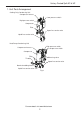
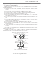
Unitary Ducted Split AC & HP 1. Unit Parts Arrangement Cooling Only Condensing Unit Compressor harness Low pressure switch High pressure switch Compressor Filter Vapor line service valve Liquid line service valve Fig.1 Heat Pump Condensing Unit High pressure switch Low pressure switch Compressor harness Compressor Filter Throttle Revesing valve Vapor line service valve Nozzle for adding freon Liquid line service valve Fig.2 For more details visit www.MrCool.
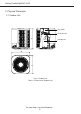
Unitary Ducted Split AC & HP 2. Physical Dimension 2.1 Outdoor Unit Fan motor H Axial flow fan Compressor D W Fig.3—Outdoor Unit Table 1—Dimension of Outdoor Unit For more details visit www.MrCool.
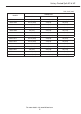
Unitary Ducted Split AC & HP Unit: Inch (mm) DIMENSION MODEL H D W MAC13018 24"(610) 21-1/2"(546) 21-1/2"(546) MAC13024 24-1/2"(620) 24"(610) 24"(610) MAC13030 29"(735) 24"(610) 24"(610) MAC13036 29"(735) 28"(710) 28"(710) MAC13042 29"(735) 28"(710) 28"(710) MAC13048 29"(735) 28"(710) 28"(710) MAC13060 33-1/2"(850) 29-1/2"(750) 29-1/2"(750) MHP13018 24-1/2"(620) 24"(610) 24"(610) MHP13024 24-1/2"(620) 24"(610) 24"(610) MHP13030 29"(735) 28"(710) 28"(710) MHP13036
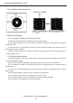
Unitary Ducted Split AC & HP 2.2 Installation Clearance Data >3000mm (120inch) Floor >1000mm (40inch) >1000mm (40inch) >1000mm (40inch) >800mm (32inch) >1000mm (40inch) Floor Fig.4 2.3 Units Installation 2.3.1 Installation Positions of Condensing Units ● Outdoor Unit must be fixed on stable and solid surface of floor. ● Don’t install Outdoor Unit under window or between buildings, and prevent the operation noise from room.
Unitary Ducted Split AC & HP 2.4 Installation Recommendations NOTE: In some cases noise in the living area has been traced to gas pulsations from improper installation of equipment. 1). Locate unit away from windows, patios, decks, etc. where unit operation sound may disturb customer. 2). Ensure that vapor and liquid tube diameters are appropriate for unit capacity. 3). Run refrigerant tubes as directly as possible by avoiding unnecessary turns and bends. 4).
Unitary Ducted Split AC & HP 3. Brazing Connections 3.1 Preparation the Line Refer to Table 2 for field tubing diameters. The pipe must remain round. Do not crimp end of the line. Table 2. Refrigerant Line Set Inches (mm) Valve Field Connections Model Liquid Line Vapor Line MAC13018 MHP13018 5/8 in. (16 mm) MAC13024 MHP13024 MAC13030 MHP13030 MAC13036 3/8 in. (9.5 mm) 3/4 in. (19 mm) MHP13036 MAC13042 MHP13042 7/8 in. (22 mm) MAC13048 MHP13048 MAC13060 MHP13060 1/2 in.
Unitary Ducted Split AC & HP 3.2 Cap and Core Removal Remove service cap and core from both the vapor and liquid line service ports. Service port core Service port core Service port cap Service port cap Vapor line service valve Liquid line service valve Fig.7 3.3 Attach Gauge Flow regulated nitrogen (at 1 to 2 psig) through the low−side refrigeration gauge set into the liquid line service port valve, and out of the vapor line service port valve.
Unitary Ducted Split AC & HP 3.5 Preparation for Next Step After all connections have been brazed, disconnect manifold gauge set from service ports. Apply water saturated cloths to both services valves to cool piping. Once piping is cool, remove all water saturated cloths.Reinstall service cap and core.Refer to the unit installation instructions for the next step in preparing the unit. 4.
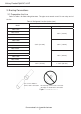
Unitary Ducted Split AC & HP 5. Operating Gauge Set and Service Valves These instructions are intended as a general guide and do not supersede local codes in any way. Consult authorities who have jurisdiction before installation. 5.1 Torque Requirements When servicing or repairing heating, ventilating, and air conditioning components, ensure the fasteners are appropriately tightened. Table 4 lists torque values for fasteners.
Unitary Ducted Split AC & HP Service port cap To outdoor unit Service port core ( Valve stem shown closed) Insert hex wrench here (valve stem shown open) Insert hex wrench here To indoor unit Stem cap Service valve (Back-seated opened) Service valve (Front-seated closed) Fig.11 5.5 To Access Service Port A service port cap protects the service port core from contamination and serves as the primary leak seal. 1). Remove service port cap with an appropriately sized wrench. 2).
Unitary Ducted Split AC & HP 6. Recovering Refrigerant from Existing System 6.1 Disconnect Power Disconnect all power to the existing outdoor unit at the disconnect switch or main fuse box/ breaker panel. 6.2 Connect Manifold Gauge Set Connect a gauge set, clean recovery cylinder and a recovery machine to the service ports of the existing unit. Use the instructions provided with the recovery machine to make the connections.
Unitary Ducted Split AC & HP Perform the following task: a. Start the existing HCFC−410A system in the cooling mode and close the liquid line valve. b. Use the compressor to pump as much of the existing HCFC−410A refrigerant into the outdoor unit until the outdoor system is full. Turn the outdoor unit main power OFF and use a recovery machine to remove the remaining refrigerant from the system.
Unitary Ducted Split AC & HP port of the manifold gauge set. Open the valve on the HFC−410A cylinder (vapor only). 2). Open the high pressure side of the manifold to allow HFC−410A into the line set and indoor unit. Weigh in a trace amount of HFC−410A. [A trace amount is a maximum of two ounces (57 g) refrigerant or three pounds (31 kPa) pressure]. Close the valve on the HFC−410A cylinder and the valve on the high pressure side of the manifold gauge set. Disconnect the HFC−410A cylinder. 3).
Unitary Ducted Split AC & HP testing procedure. NOTE: The term absolute pressure means the total actual pressure within a given volume or system, above the absolute zero of pressure. Absolute pressure in a vacuum is equal to atmospheric pressure minus vacuum pressure. 3). When the absolute pressure reaches 23,000 microns (29.
Unitary Ducted Split AC & HP 7.1 Size Circuit And Install Disconnect Switch Refer to the unit nameplate for minimum circuit ampacity, and maximum fuse or circuit breaker (HACR per NEC). Install power wiring and properly sized disconnect switch. Main Fuse Box/Breaker Panel Disconnect Switch Fig.16 NOTE: Units are approved for use only with copper conductors. Ground unit at disconnect switch or to an earth ground. 7.
Unitary Ducted Split AC & HP Table 5 WIRE RUN LENGTH AWG# INSULATION TYPE LESS THAN 100’ (30 METERS) 18 Temperature Rating MORE THAN 100’ (30 METERS) 16 35°C Minimum A Run 24VAC control wires through cutout with grommet. B Run 24VAC control wires through wire tie. C Make 24VAC control wire connections.
Unitary Ducted Split AC & HP MHP13036 208/230/1/60 1 15.08 64 1.7 35 AWG12 MHP13042 208/230/1/60 1 17 112 1.7 35 AWG10 MHP13048 208/230/1/60 1 21 115 1.7 45 AWG10 MHP13060 208/230/1/60 1 24.5 134 2.3 50 AWG8 Electric Wiring Design Model:MAC13018; MAC13024; MAC13030; MAC13036; MAC13042; MAC13048; MAC13060. POWER 208/230V L1 1PH 60HZ L2 Ground T1 T2 L1 L2 C C R R W1 Y1 Y1 O THERMOSTAT G Fig.18 Model: MHP13018; MHP13024; MHP13030; MHP13036.
Unitary Ducted Split AC & HP L1 XT1 POWER 208/230V 1PH 60HZ L1 L2 L2 Ground G Outdoor Unit C R R Y1 Y1 O W1 O W1 THERMOSTAT G XT2 C Fig.20 18-36k Circuit Diagram Model:MAC13018; MAC13024; MAC13030; MAC13036.
Unitary Ducted Split AC & HP 42-60k Circuit Diagram Model:MAC13042; MAC13048; MAC13060. THERMOSTAT ~ Lug Plate 1 OUTDOOR UNIT ~ Fig.22 18-36k Circuit Diagram Model: MHP13018; MHP13024; MHP13030; MHP13036.
Unitary Ducted Split AC & HP 42-60k Circuit Diagram Model:MHP13042; MHP13048; MHP13060. Fig.24 8. System Refrigerant This section outlines procedures for: ● Connecting gauge set for testing and charging. ● Adding or removing refrigerant. 8.1 Gauge Set (Cooling Only) Connections for testing and charging. A Close manifold gauge set valves and connect the center hose to a cylinder of HFC−410A. Set for liquid phase charging.
Unitary Ducted Split AC & HP Figure 25. Gauge Set Setup and Connections for cooling only 8.2 Gauge Set (Heat Pump) Connections for testing and charging. A Close manifold gauge set valves and connect the center hose to a cylinder of HFC−410A. Set for liquid phase charging. B Connect the manifold gauge set’s low pressure side to the true suction port. C Connect the manifold gauge set’s high pressure side to the liquid line service port. D Position temperature sensor on the suction line near the compressor.
Unitary Ducted Split AC & HP 8.3 Weigh In Calculating system charge for outdoor unit void of charge If the system is void of refrigerant, first, locate and repair any leaks and then weigh in the refrigerant charge into the unit.
Unitary Ducted Split AC & HP START: Measure outdoor ambient temperature 40℉(4.4℃) and above 39℉(3.
Unitary Ducted Split AC & HP Table 8.
Unitary Ducted Split AC & HP 80(27) 282/138 291/142 306/139 85(29) 302/139 312/143 327/140 90(32) 326/140 335/144 351/141 95(35) 349 / 141 359 / 145 376 / 142 100(38) 374 / 142 384 / 146 401 / 143 105(41) 399 / 143 411 / 148 426 / 145 110(43) 428 / 145 439 / 149 452 / 146 115(46) 455 / 146 468 / 150 484 / 148 *IMPORTANT—These are most popular match−up pressures. Indoor match up, indoor air quality, and indoor load cause pressures to vary.
Unitary Ducted Split AC & HP 9. Unit Control 9.1 Mainboard Description Pressure switch circuit connections 24V terminal strip connections Sensor plug in (Discharge sensor) 24V terminal strip connections +12V common terminal Diagnostic leds Fig.28 Mainboard Description for cooling only Temp. Sensors plug in +12V common terminal Pressure switch circuit connections Disagnostic display 24V terminal strip connections 24V terminal strip connections Connections for fan motor Fig.
Unitary Ducted Split AC & HP 9.2 Terminal Description Table 10. Demand Control Board Description for cooling only unit ID Description X12(Y-OUT) 24 VAC output connection for compressor operation X7(LPP) Connection for low−pressure switch X10(HPP) Connection for high−pressure switch X3(Y) 24 VAC input for compressor operation CN3(T-PIPE) Connection for discharge temperature sensor.
Unitary Ducted Split AC & HP 9.3 Control Flowchart Cooling Operation Heating Operation Power On Power On Choo se cooling model Choo se heaingt model Indoo r fan run N Satisfying open comp. condition Satisfying open Comp. condition Y N Comp. and outdoo r fan run Y Comp. and outdoo r fan run Temp of indoo r ≥Set temp Temp of indoo r N N ≤Set temp Y Y Comp. and outdoo r fan stop Comp. and outdoo r fan stop Y Y Comp. stop for 3 min N For more details visit www.MrCool.com 29 Comp.
Unitary Ducted Split AC & HP 9.4 Error Analysis COOLING ONLY DEMAND CONTROL BOARD DIAGNOSTICS The state (Off, On, Flashing) of two LEDs on the control board (DS1 [Red] and DS2 [Red]) indicate diagnostics conditions that are described in table 12. See table 12 to determine control board operational conditions and to diagnose cause and solution to problems. Table 12.
Unitary Ducted Split AC & HP 0.5s Circulating Flash Continuous Light Air discharge hightemperature protection of compressor Exhaust overtemperature Protection The exhaust temperature is higher than 125°C for more than 5s, the system will be shut down. After stopping the compressor for 3 mins, if the exhaust temperature is lower than 90°C for more than 5s, the compressor will re-start. For the first two faults within 30 minutes, the unit can be recovered automatically.
Unitary Ducted Split AC & HP Exhaust overtemperature protection The exhaust temperature is higher than 125°C for more than 5sec, the system will be shut down. After stopping the compressor for 3 mins, if the exhaust temperature is lower than 90°C for more than 5 sec, the compressor will re-start. For the first two faults within 30 minutes, the unit can be recovered automatically. If over three times, the unit cannot be recovered automatically.
Unitary Ducted Split AC & HP 9.5 Setting on Defrost Control PCB (for Heat Pump unit only) There are 5 different defrost control setting you can choose by change the dip switch located on Defrost Control PCB. ON DIP 12 ON 3 DIP 12 000 ON 3 DIP ON 12 3 010 Fig.
For more details visit www.MrCool.