
mrcool 13seer r410 cond install manual 4web

Unitary Ducted Split AC & HP
28
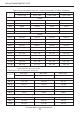
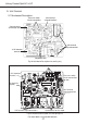
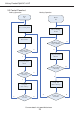
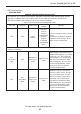
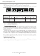
9.2 Terminal Description
Table 10. Demand Control Board Description for cooling only unit
ID Description
X12(Y-OUT) 24 VAC output connection for compressor operation
X7(LPP) Connection for low−pressure switch
X10(HPP) Connection for high−pressure switch
X3(Y) 24 VAC input for compressor operation
CN3(T-PIPE) Connection for discharge temperature sensor.
X16(C) 24 VAC system common
X15(R) 24 VAC system power input
X8(+12V) Connection for low−pressure switch Connection for high−pressure switch
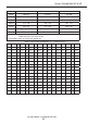
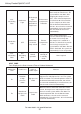
Table 11. Demand Control Board Description for Heat pump unit
ID Description
X1(W-OUT) Auxiliary electrical heater output
X2(O) Connection for detecting the 24VAC control signal of 4-way valve
X3(Y) Connection for detecting the 24VAC signal for compressor
X7(LPP) Connection for low pressure switch
X8(+12V) Connection for low pressure switch, Connection for high pressure switch
X10(HPP) Connection for high pressure switch
X12(Y-OUT) 24 VAC output interface for compressor operation
X13(O-OUT) 24 VAC output interface for 4-way valve operation
X14(N) 220 VAC N input of fan motor
X15(R) 24 VAC system power input
X16(C) 24 VAC system common
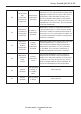
CN1(T-DF) Connection for temp.sensor of condenser
CN2(OUTROOM) Connection for ambient temp.sensor
CN3(T-PIPE) Connection for discharge temp.sensor
CN5(TUBE) Connect 20k xed resistance into reserved interface
K2-2(OFAN-H) 220VAC output for high speed of fan motor
K2-4(AC-L) 220VAC L input for high speed of fan motor
K5-2(OFAN-L) 220VAC output for low speed of fan motor
K5-4(AC-L) 220VAC L input for low speed of fan motor
For more details visit www.MrCool.com