Please read this manual carefully before installation and keep it for future reference. & mRCOoOOoL COMFORT MADE SIMPLE Installation Manual Packaged Heat Pump 14 SEER R410A (2-5 Tons) RECOGNIZE THIS SYMBOL AS AN INDICATION OF IMPORTANT SAFETY INFORMATION ZA WARNING These instructions are intended as an aid to qualified, licensed service personnel for proper installation, adjustment and operation of this unit.
SNE When you see the symbols blow on the labels or in ‘the manuals, be alert to the potential or immediate hazards of personal injury, property and/or product damage, It is the owner's or Installer's responsibility to comply with all safety instructions and information accompanying these symbols.
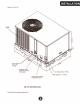
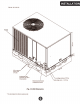
LAE E ES INSPECTION As 5001 as unit is received, it should be inspected arid noted for possible shipping damage during transportation, it is carrier's responsibility to cover the lost of shipping damage. Manufacturer or distributor will not accept the medalist from dealer for any transportation damage, LIMITATIONS Refer to Fg.
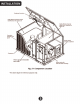
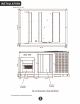
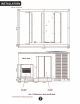
WAP ET a [0] hit shew 042; Hoe = Bottom: View . 14308 = © ! Ser a Back View aan [id atg Side Si pity hairspring Fig.
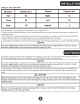
INSTALLATION Table 2-1: Unit Clearance Duct clearance: 1 inch clearance for all sides of air supply duct, 1. Units must be Installed outdoors, Over hanging structure or shrubs should riot obscure condenser air discharge outlet, 2. The minimum clearance without economizer/fresh air damper, For distance with econormicer/fresh air damper, please refer to the installation instructions provided with the accessory, 3. Units may be installed on combustible Doors made from wood or sass roof covering materials.
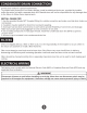
CONDENSATE DRAIN CONNECTION Consult focal codes for special requirements. To provide extra protection from water damage, install an additional drain pan, provided by installer, unfed the entire Unit with a separate drain line, Manufacturer will riot be responsible for any darn ages die to the failure to follow these retirements. INSTALL DRAIN PIPE 1, Use the provided female NPT threaded fitting for outside connection and make sure that drain holes are not hijacked, 2.
ELECTRICAL WIRING POWER WIRING 1. Proper electrical power should be available at unit, Voltage tolerance should not be over 10% from rating voltage. 2. 1 any of the wire must be replaced, replacement wire must be the same type as shown in nameplate, wiring diagram and electrical data sheet. 3. Install a branch rut disconnect of adequate size to handle starting current, located within sight of, and readily accessible to the unit.
ELECTRICAL WIRING UNIT.CONTROL BOARD THERMOSTAT WEATHERSTRIPPING “i ADV: ay COM Fig. 6-1 Typical Field Control Wiring Diagram Wire be used with heat pump system only, reversing valve energizes at the heating mode, and ut off at the cooling mode. *& Minimum wire size of 18 AWG wire should be used for all field installed 24 volt wire, * Only required or units with supplemental electric heat, | £\ WARNING | Label all wire prior to disconnection when servicing controls, Wiring errors can cause improper and dang
AIRFLOW PERFORMANCE Airflow performance data is based on cooling performance with a coil and no filter in place.
AIRFLOW PERFORMANCE Table 7-1 Duct Misapplication) (Continued) al HAA ARCHERY 1 AER Aussie 7 Ta tile 7-2 Duct Misapplication) 1516718) 13231624) 1250(590) B74 Hib 55 fs 218 14% 4 ELE TARAZED 15880155) a) 6 pier
AIRFLOW PERFORMANCE Table 7-2 Duct Misapplication) (Continued) 3 1 * The above airflow data for reference only. * In any sanitation , the airflow of the Unit should be in the range of 80% to 130% of 400CFM/ Ton. » The air distribution system has the greatest effect on airflow, The duct system is totally controlled by the contractor. For this reason, the contractor should use only industry-recognized procedures.
AIRFLOW PERFORMANCE Table 7-3 Refrigerant charge for H/P system roe ling Mode tor Ambient 1 Mok 85 0 5 Dis Rotisseries 185 sur | B16 | fom 300 Vance Defects de Precision Baseness psi) 2% 238.
AIRFLOW PERFORMANCE Table 7-5 Refrigerant charge for H/P system Ei] Coming pes Hed £6 disembowelment Table 7-6 Refrigerant charge for H/P system Vance Detected de Precision Assailant psi) 188 161 157 153 13 109 105 deniable De Charge de temperance.
AIRFLOW PERFORMANCE Table 7-11 Refrigerant charge for H/P system 48 Cooling Mode Mats Die Disfranchisement ih Prague: Service. Detects de Precision’ Vain me Détecée de Profession Baseless psi) Table 7-12 Refrigerant charge for H/P system is Heating Charge. Chart Tableau De: Ghat de Chauffeur Heating Mads: Ir door Dry Bulb Temperature i Temperate Interior au Thermometric: secant kL Rode so. f.
SYSTEM OPERATION COMPRESSOR CRANKCASE HEATER (OPTIONAL) Refrigerant migration during the off cycle can result in a noisy start up, Add a crankcase heater to minimize refrigeration migration, and to help eliminate any start Up noise oF bearing “Wash out”, All heaters are located on the lower Half of the compressor shells Its purpose is to drive refrigerant from the compressor shell during long off gentles, thus preventing damage to the compressor duding start-up.
DEFROST MODE® (For HP system only) SYSTEM OPERATION Defrosting condition: When JUMP switch is setts "17, the defrost mode will start if one of following conditions is satisfied: 1. Compressor keeps running, when This» 284 °F and and last for 40 minutes; 2. Compressor Keeps running, when T4 is < 28.4 °F and *F.and last for 50 minutes, * When defrosting actions, if the electrical heater kit is installed, the unit would deliver the Aux. heater operation signaler to the electrical heater kit.
SYSTEM OPERATION THERMOSTAT SIGNALS Table 8-1; Thermostat Signals RESET Blower instant ON Sower 50 5a delay OFF Tower instant DN a Hater bank { electronics Li Heater hank 1 cic stat GFF Bloom 00s delay OFF Blower hist Gh Heater 1 insane ON Heater 2 instant G8 Caw awe Blows 50 oe delay OFF Hater instant OFF Heater instant GET Blower: instant ON Compressor and algorithm Rab SHRED Compressor ANd GOOD Tat SINE OFF.
OPERATION CHECK-UP Coaling Start tip 1. Turn thermostat to OFF and turn power to ON 2. Turn ON thermostat and set as high as possible 3 Turn Fan switch ON and indoor blower should run 4, Tui fan switch to AUTO, system switch to COOL and thermostat temperature setting below room temperature. Unit wouldst ru In COOLING mode, Heating Startup After normal coding rin 1. Turn thermostat switch to HEAT. After unit stops, Walt about 5 minutes, 2. Turn thermostat setting above room temperature.
N30 031 HVE 8 EO SOH HO SARI TUNING HOYDENISH ¥FL= HOVE I iri Nos EL REVISE JI i SR POOR liege up do IRON AG. Opt pi oy eon Uc ple el ANT, Sag pes pal GB op. | “SHIM CREDITOR SY.
7. AT Y cooler COMFORT MADE SIMPLE Installation Manual Packaged Heat Pump 14 SEER R410A (2-5 Tons) The design and specifications are subject to change without prior notice. Consult with the sales agency or manufacturer for details.