DC Inverter U-match Series for R410A Unitary Split Air Conditioner SERVICE MANUAL Capacity: 24kBtu/h~60kBtu/h Rate Frequency: 60Hz Operation Range: Cooling: 5°F(-15°C)~129.2℉(54℃) Heating: -22°F (-30°C)~75.
Safety Notice Before using the air conditioner, please first read the instruction manual. Before installing the air conditioner, please first read the instruction manual. Before repairing the air conditioner, please first read the technical service manual.
CONTENTS Safety Notice on Maintenance.................................................................................................................. 1 Safety Notice on Operation........................................................................................................................2 1. Product Introduction............................................................................................................................... 3 1.1 Lists of Units.......................................
DC Inverter U-match Series for R410A Unitary Split Air Conditioner Safety Notice on Maintenance PROHIBITED: (1) Do not pierce or burn. (2) Please note that refrigerant may be odorless. (3) The appliance shall be stored in a room without continuously operating ignition sources (For example: open flames, an operating gas appliance or an operating electric heater). (4) Indoor unit adopts special joints that can’t be detached. The installation method is the same with the common joints.
Universal Service Manual high speed; Otherwise personal injury may occur. (5) Measure the insulation resistance after maintenance. The resistance must be 1M or higher. Bad insulation may lead to electric shock. (6) Welding and cutting work must be done in a well-ventilated place. (7) Gas appliances, heaters and other fire sources should be kept away from the installation and maintenance site. (8) Maintenance should be done according to suggestions of the manufacturer.
MRCOOL Universal Service Manual 1. Product Introduction 1.1 Lists of Units 1.1.
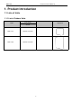
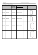
MRCOOL Universal Service Manual 1.1.2 List of Indoor Units Model Cooling/Heating Capacity (Btu/h) Power Supply Appearance V/Ph/Hz Airhandler MDUI18024 24000/24000 208/230V-1Ph-60Hz Airhandler MDUI18036 36000/36000 208/230V-1Ph-60Hz Airhandler MDUI18048 48000/48000 208/230V-1Ph-60Hz Airhandler MDUI18060 54000/54000 208/230V-1Ph-60Hz Note: 1 Ton =12000Btu/h = 3.
MRCOOL Universal Service Manual 1.
MRCOOL Universal Service Manual 2. Control 2.1 Operation Mode 2.1.
MRCOOL Universal Service Manual 2.1.
MRCOOL Universal Service Manual 2.2 Control Mode 2.2.1 Based Control 2.2.1.1 Compressor Control When cooling or heating mode is turned on, indoor fan will run for a while before the compressor starts. Under different modes, the compressor can only be stopped after running for some time (special cases excluded). This is to protect the compressor from frequent start or stop. Once the compressor is stopped, it must not be restarted right away. Please wait for a few minutes. 2.2.1.
MRCOOL Universal Service Manual and outdoor and indoor fan will both stop. When the temperature sensed by outdoor tube temperature sensor reaches the preset value of defrosting stop, system will quit defrosting. The 4-way valve will switch back to the heating condition, compressor and outdoor unit fan restart. 2.2.2.2 Oil Return Control If the unit is running at low frequency for a long time, system will enable oil return control.
MRCOOL Universal Service Manual detected open for continuously a little time. Under discharge high temperature protection, system will be shut down and display error code E4. When discharge high temperature protection occurs, system will restore operation if the discharge high temperature sensor is detected to be reclosed within a few minutes after shutdown. If discharge high temperature protection occurs for several times in a period of time, system will not restore operation automatically.
MRCOOL Universal Service Manual By setting the Forcible mode dial codes of the condensing unit, the air conditioner can quickly increase the capacity output and ensure reliable operation in a short time, so as to meet the user's demand for the indoor temperature to quickly reach the set temperature. Energy saving mode is achieved by setting the condensing unit operating mode to operate the air conditioner within a small load range.
MRCOOL Universal Service Manual Level 1 (Default) Level 2 Level 3 2.3.5 Forced Defrost Control Press and hold "SW1" for about 5s to enter the first level menu of the debugging mode, the outdoor unit mainboard LED displayer flashes. Under the first level menu, short press "SW1" to switch various functions. After switching to "06", short press "SW2" or "SW3" to enter the forced defrosting mode, "ON" means open, "OF" means close, and then short press "SW1" to save.
MRCOOL Universal Service Manual indicates that shut down the forced cooling / heating mode. And then short press "SW1" to save. During debugging, if no operation is performed within 10s, the debugging mode interface will be exited. 2.3.8 Thermostat Functions Thermostat model: XE70-00/E1, please refer to the thermostat instruction manual for all functions.
MRCOOL Universal Service Manual 3. Troubleshooting 3.1 Wiring Diagrams The following electric diagram is for reference only. Please refer to diagram sticked on the unit as the latest version. 3.1.
MRCOOL Universal Service Manual Model: MDUO1860 15
MRCOOL Universal Service Manual 3.1.
MRCOOL Universal Service Manual 3.2 PCB Layout 3.2.1 Interface Indoor unit: Model: MDUI18024, MDUI18036, MDUI18048, MDUI18060, Mainboard No. Printing Interface No.
MRCOOL 7 Universal Service Manual X10(O_SCAN) 4-Way check 14 Transformer Live wire output X4(R) Pinboard No. Printing Interface No.
MRCOOL Universal Service Manual Outdoor unit: Model: MDUO18036、MDUO18060 Mainboard No. Printing Interface No. Printing Interface 1 AC-L Live wire input 11 H-PRESS high pressure interface 2 AC-N Neutral wire input 12 LPP System low pressure protection interface 3 HEAT_TI E_B Chassis heating belt 13 HPP System high pressure protection interface 14 T_SENSOR2 2. Outdoor tube temperature sensor interface 4. Outdoor ambient temperature sensor interface 6.
MRCOOL Universal Service Manual 6 VA Electromagnetic valve 16 interface COM7 Unit communication interface 7 FA Electronic expansion 17 valve interface CN6 GPRS interface 8 FA1 Electronic expansion valve 1 interface 18 Refrigerant heat dissipation COM-MANUA L Thermostat interface 9 COMM1 Drive communication 19 interface DC_MOTOR1 DC_MOTOR2 DC motor output 10 L-PRESS low pressure sensor 20 interface PWR1 310V DC interface communication power supply Drive Board: Model: MDUO1836 13
MRCOOL Universal Service Manual 6 COMM Communication terminal, same 15 with COMM1 V Compressor V phase terminal 7 PWR Drive power supply terminal 16 W Compressor W phase terminal 8 DC-MOTOR1 DC fan terminal 17 JTAG1 Programming testing) 9 DC-BUS1 Model: MDUO1860 interface (for Power discharge terminal (for testing) 12 7 4 2 1 3 8 5 13 11 10 6 9 No. Printing Interface No.
MRCOOL Universal Service Manual Filtering Board: Model: MDUO1836 2 ⑩ 1 5 ⑩ ⑩ 6 ⑩ 7 3 ⑩ ⑩ 4 ⑩ No. Printing Interface No.
MRCOOL Universal Service Manual 3 E Filtering board ground wire terminal 4 E1 Filtering board (reserved) 5 DC-BUS Power discharge terminal (for testing) grounding hole 8 L-OUT1 Power output live wire terminal 9 L-OUT Power output live wire terminal 3.2.2 IPM, PFC Testing Method 3.2.2.1Method of Testing IPM Module (1) Preparation before test: prepare a universal meter and turn to its diode option, and then remove the wires U, V, W of the compressor after it is powered off for one minute.
MRCOOL Universal Service Manual 24
MRCOOL Universal Service Manual MDUO1860 25
MRCOOL Universal Service Manual 3.3 Error Code No.
MRCOOL Universal Service Manual 3.4 Troubleshooting 3.4.1 “E1” Compressor High Pressure Protection Error display: ODU mainboard LED displayer Error judgment condition and method: It is judged through the action of high pressure switch. If the high pressure switch is cut off, it is judged that high pressure is too high and the system stops operation for protection.
MRCOOL Universal Service Manual Troubleshooting: 3.4.
MRCOOL Universal Service Manual It is judged through the action of low pressure switch. If the low pressure switch is cut off, it is judged that low pressure is too low and the system stops operation for protection.
MRCOOL Universal Service Manual 3.4.3 “E4” Compressor Air Discharge High-temperature Protection Error display: ODU mainboard LED displayer Error judgment condition and method: Test the compressor discharge temperature through compressor discharge pipe and shell top temperature sensor.
MRCOOL Universal Service Manual Troubleshooting: 3.4.4 “F2” Condenser Temperature Sensor Error Error display: ODU mainboard LED displayer Error judgment condition and method: Sample the AD value of temperature sensor through temperature sensor detecting circuit and judge the range of AD value, If the sampling AD value exceeds upper limit and lower limit in 5 seconds continuously, report the error.
MRCOOL Universal Service Manual Possible reason: ■Poor contact between temperature sensor and terminal in mainboard interface ■Temperature sensor is abnormal ■Detecting circuit is abnormal Troubleshooting: Note: Please refer to Appendix 1 for the relation between temperature and resistance of temperature sensor. 3.4.
MRCOOL Universal Service Manual Troubleshooting: Note: Please refer to Appendix 1 for the relation between temperature and resistance of temperature sensor. 3.4.6 “F4” Discharge Temperature Sensor Error Error display: ODU mainboard LED displayer Error judgment condition and method: Sample the AD value of temperature sensor through temperature sensor detecting circuit and judge the range of AD value, If the sampling AD value exceeds upper limit and lower limit in 5 seconds continuously, report the error.
MRCOOL Universal Service Manual Troubleshooting: Note: Please refer to Appendix 1 for the relation between temperature and resistance of temperature sensor. 3.4.7 “F6” ODU Tube Temperature Sensor Error Error display: ODU mainboard LED displayer Error judgment condition and method: Sample the AD value of temperature sensor through temperature sensor detecting circuit and judge the range of AD value, If the sampling AD value exceeds upper limit and lower limit in 5 seconds continuously, report the error.
MRCOOL Universal Service Manual Troubleshooting: Note: Please refer to Appendix 1 for the relation between temperature and resistance of temperature sensor. 3.4.8“EE” ODU Memory Chip Error Error display: ODU mainboard LED displayer Error judgment condition and method: If ODU mainboard cannot read the memory chip, this error will be reported. Possible reason: ■ Memory chip on the ODU mainboard is damaged. ■. Memory chip is weakly welded. ■. Memory chip lead is short-circuited.
MRCOOL Universal Service Manual 3.4.9 “H4” Overload Error display: ODU mainboard LED displayer Error judgment condition and method: When condensing pressure is higher than the protection value, system will report overload protection. Possible reason: ■Cooling ODU heat exchanger is blocked or heat exchange is bad. ■Heating IDU heat exchanger is blocked or heat exchange is bad. ■Operating temperature is too high. ■System charging quantity is too much.
MRCOOL Universal Service Manual Troubleshooting: H4 Overload YES Outdoor heat exchanger is blocked Remove the obstacle NO YES Indoor heat exchanger is blocked . Remove the obstacle NO Ambient temperature is out of the operation range YES Normal protection. No need to handle it. YES Release a proper amount of refrigerant NO Too much charging quantity. NO Replace the drive board YES Error still exists? Replace the compressor 3.4.
MRCOOL Universal Service Manual ■Drive board compressor current sampling circuit element is damaged or drive chip current sampling AD terminal is abnormal. ■Compressor is damaged. Troubleshooting: 3.4.11 “H6” DC Fan Error Error display: ODU mainboard LED displayer Error judgment condition and method: Mainboard doesn’t receive the signal of outdoor fan within 30s after the outdoor fan starts up. Possible reason: ■Outdoor fan wiring terminal is not correctly connected to the mainboard.
MRCOOL Universal Service Manual Troubleshooting: 3.4.12 “H7” Driver Out-of-Step Protection Error display: ODU mainboard LED displayer Error judgment condition and method: During operation, it can’t detect the rotor position and stops output. Or the actual running speed differs too much from the set running speed. In each case, compressor runs out of step and system stops for protection. Possible reason: ■Compressor 3-phase wire connection is lack of phase or phased-reversed.
MRCOOL Universal Service Manual Troubleshooting: 40
MRCOOL Universal Service Manual 3.4.13 “HC” PFC Protection Error display: ODU mainboard LED displayer Error judgment condition and method: After power is connected, and drive chip received IPM lead F0 that is of low level, than it is IPM module malfunction. System will shut down for protection. Possible reason: ■Power grid voltage is abnormal. ■Drive board PFC module is damaged. ■Drive board IPM module’s 15V power supply is lower than 13.5V.
MRCOOL Universal Service Manual 3.4.14 “Lc” Startup Failure Error display: ODU mainboard LED displayer Error judgment condition and method: Check the error code on nixie tube of ODU main control board.
MRCOOL Universal Service Manual 3.4.15 “P0” Driver Reset Protection Error display: ODU mainboard LED displayer Error judgment condition and method: Drive board chip resets and starts initialization. After the drive board is energized for 5s, it detects that the chip resets again. In this case, it can be judged as drive chip reset protection. Possible reason: ■3.3V drive chip supply voltage drop. ■TRST lead of JTAG programming is interrupted. Troubleshooting: P0 Driver reset protection 3.
MRCOOL Universal Service Manual Troubleshooting: 3.4.17 “P6” Master Control and Driver Communication Error Error display: ODU mainboard LED displayer Error judgment condition and method: If there is no other malfunction and the communication between master control and driver is cut off for 30s, then it can be judged that the communication between master control and driver is faulted. System will shut down for protection.
MRCOOL Universal Service Manual Troubleshooting: 3.4.18 “P7” Driver Module Sensor Error Error display: ODU mainboard LED displayer Error judgment condition and method: If IPM or PFC module temperature is lower than the set protection value, then it can be judged that driver module sensor error occurs and system will shut down for protection. Possible reason: ■Module temperature sensor is short-circuited or broken-circuited.
MRCOOL Universal Service Manual 3.4.19 “P8” Driver Module High Temperature Protection Error display: ODU mainboard LED displayer Error judgment condition and method: If IPM module temperature or PFC module temperature exceeds the set protection value, then it can be judged that driver module temperature is too high and system will shut down for protection. Possible reason: ■Thermal grease is not applied or not evenly applied to the module, or there is other substance on the back of the module.
MRCOOL Universal Service Manual ■Drive board PFC current sampling circuit element is damaged or drive chip PFC current sampling AD terminal is abnormal. Troubleshooting: 3.4.21 “Pc” Driver Current Error Error display: ODU mainboard LED displayer Error judgment condition and method: After power charging, if offset voltage average is detected to exceed 12.5% of 1.65V in 1s, then it can be judged that current detection (or current sensor) circuit is faulted. System will shut down for protection.
MRCOOL Universal Service Manual 3.4.22 “PL” Bus Low-Voltage Protection Error display: ODU mainboard LED displayer Error judgment condition and method: When compressor is running and there is no other malfunction, if busbar voltage is lower than the set value for low voltage protection, then it can be judged that bus low-voltage protection occurs. System will shut down for protection. Possible reason: ■Voltage of power grid is abnormal.
MRCOOL Universal Service Manual Troubleshooting: 3.4.24 “PU” Charge Loop Error Error display: ODU mainboard LED displayer Error judgment condition and method: When the charge loop starts to get charged and the busbar voltage cannot reach the set value in a certain period of time, then it can be judged that charge loop error exists. System will shut down for protection. Possible reason: ■Voltage of power grid is abnormal. Voltage is too low. ■Drive board charge loop element is abnormal.
MRCOOL Universal Service Manual 3.4.25 “ee” Drive Memory Chip Error Error display: ODU mainboard LED displayer Error judgment condition and method: If power is connected but the drive board with memory chip cannot detect the memory chip or read the memory chip data correctly, then it can be judged that drive memory chip error exists. Possible reason: ■The drive board that needs memory chip is not installed with the memory chip. ■The lead or connector of memory chip is badly welded or short-circuited.
MRCOOL Universal Service Manual 3.4.
MRCOOL Universal Service Manual 52
MRCOOL Universal Service Manual 3.5 Failures Not Caused by Errors (1) If your air conditioner fails to function normally, please first check the following items before maintenance: Problem Cause Corrective measure If you turn off the unit and then immediately turn it on, in order to protect the compressor and avoid system overload, compressor will Please wait for a while. delay running for 3min. The air conditioner can't run. Bad cooling or heating effect. Wire connection is wrong.
MRCOOL Universal Service Manual (2) The following situations are not operation failures. Problem Mist comes from the air conditioner. The air conditioner generates some noise. Time of occurrence Cause If the unit is running under high humidity, During operation. the wet air in the room will be quickly cooled down. System switches to heating mode after Defrosting process will generate some defrosting. water, which will turn to water vapor.
MRCOOL Universal Service Manual 4. Maintenance 4.1 System Diagram Thermal Expansion Valve First level EXV Second level EXV One Way Valve Evaporator Condensor Low Pressure Switch Accumulator Pressure Sensor 4-Way Valve High Pressure Switch Electromagnetic Valve Compressor Cooling Heating Gas-liquid separator 4.2 Connection Pipe Vacuum Pumping NOTICE 1 Make sure the outlet of vacuum pump is away from fire source and is well-ventilated.
MRCOOL Universal Service Manual (6) Wait for 10min to see if the system pressure can remain unchanged. If the pressure increase, there may be leakage. (7) Slightly open the liquid valve and let some refrigerant go to the connection pipe to balance the pressure inside and outside of the connection pipe, so that air will not come into the connection pipe when removing the hose. Notice that the gas and liquid valve can be opened fully only after the manifold valve assembly is removed.
MRCOOL Universal Service Manual 4.3 Refrigerant Charging Pre-charging Step 1: Connect the high pressure gauge line to the valve of liquid pipe and connect the low pressure gauge line to the valve of gas pipe. Connect the middle gauge line to the vacuum pump. Power on the vacuum pump and perform vacuum drying. Step 2: After vacuum drying, close the high and low pressure gauge valves. Then remove the middle gauge line from the connector of vacuum pump. Then connect to the refrigerant tank.
MRCOOL Universal Service Manual Step 1: Close the valve of refrigerant tank. First remove the pressure gauge lines and connect the outdoor unit to the indoor unit. Then reconnect the pressure gauge lines. Connect the low pressure gauge line to the other joint of gas valve and connect the high pressure gauge line to the liquid valve. Connect the middle gauge line to the vacuum pump. Power on the vacuum pump and perform vacuum drying.
MRCOOL Universal Service Manual 4.4 Maintenance of Major Components 4.4.1 Replacement of thermostat Please refer to the instruction manual of thermostat XE70-00/E1. 4.4.2 How to replace the compressor 4.4.2.1 Diagnosis of compressor failure A. On condition that the unit can be started up Step 1: If the unit can be started up, then start it up to check the current of the faulted compressor. Use a pressure gauge to measure the pressure of the big and small valves.
MRCOOL Universal Service Manual and you can feel the movement of the valve spool. In the last stage of the reset process, you will hear the click of the valve and feel its vibration. Electronic expansion Touch the electronic expansion valve: a. Touch the top of the electronic expansion valve and you can feel its move as it is reset upon startup. b. Make sure the coil is fixed firmly. (2) 4-way valve: During normal operation, the 4 copper tubes that connect to the valve will have different temperature.
MRCOOL Universal Service Manual D- Connect to the exhaust side Caution! High temperature! Labels on the 4-way valve: D-connect to the exhaust side; E-connect to the evaporator of indoor unit; S-connect to the inhalation side of the liquid separator; C-connect to the condenser; When the system is in cooling mode, C-the pipeline is with high pressure and high temperature; E, S-the pipeline is with low pressure and low temperature; When the system is in heating mode, E-the pipeline is with high pressure and
MRCOOL Universal Service Manual Refer to the following table for the resistance between any two terminals: Compressor model QXFT-F310zN450 QXAU-F516zX440A UV Winding VW Winding WU Winding resistance resistance resistance 0.79±7%Ω 0.79±7%Ω 0.79±7%Ω Measure the earth resistance of each wiring terminal. The resistance should be above 10 megohm. If not, we can judge that the compressor is faulted inside.
MRCOOL Universal Service Manual Make sure the rubber seals of the suction and exhaust openings of the compressor are in good condition. Make sure the electric box cover of the compressor is in good condition. NOTICE: Before replacement, make sure the nameplates and models of the compressors are identical. NOTICE: Make sure the lubricant is sealed inside the compressors. (2) Prepare relevant tools 1) Prepare nitrogen. Please strictly follow the nitrogen welding standards during the welding process.
MRCOOL 2) Universal Service Manual Prepare welding rods. Prepare some welding rods of common specifications and some special welding rods that contain more than 5% silver. They are used to weld the compressor. The suction and exhaust openings of the compressor are all connected to copper-plated steel pipes, so we need to use special welding rods and solder; 3) Prepare applicable welding tools. Please evaluate how much oxygen and acetylene should be used according to the current welding condition.
MRCOOL Universal Service Manual 1) The axial direction of the compressor should not slant at an angle larger than 20° to the horizontal direction. 2) Prevent the compressor from falling. 3) Put a transparent container (over 150ml in volume) under the exhaust pipe to collect the compressor oil, thus we can see the oil quality. (3) Put the container of compressor lubricant in a bright location and see if there is impurity and discoloration. Sniff at the compressor lubricant.
MRCOOL Universal Service Manual Note: When pouring the liquid from the separator, make sure the discharge pipe is at the lower position.Slant at an angle not larger than 20° Use a transparent container to collect the content inside the separator. Check its color, seal it well and return it to the factory for inspection.
MRCOOL Universal Service Manual pressure above 25kgf. Close the big and small valves and keep the pressure of indoor and outdoor units for more than 12h. If the pressure remains unchanged, then start vacuum pumping; otherwise, check the system for leaks again. Temperature should be considered when judging the pressure change. If temperature changes by 1 ℃ , pressure will change by 0.01MPa or so. For example, if temperature is 30℃ when nitrogen of 2.
MRCOOL Universal Service Manual Step 4: Remove the screws on the drive board of the compressor. The screws are located in the white circles as shown above in the picture. Step 5: Replace with a new compressor drive board. Before replacement, apply some silica gel on the IPM module. Step 6: Install the new compressor drive board. Fix the screws and connect the wires correctly.
MRCOOL Universal Service Manual 4.5 Removal of Major Components 4.5.1 Removal of ODU Major Components Picture Name Function Through compression, the low pressure refrigerant occupies a less space. Compressor As its pressure and temperature both rise, it becomes high pressure and high temperature refrigerant. It is the power drive of the system. 4-way valve It is used to change directions, the flow of refrigerant in cooling/heating. The power drive of the fan.
MRCOOL Picture Universal Service Manual Name Accumulator Function Flash refrigerant from liquid to gas It is used to transfer partial heat of the hot flow to the cold flow so that the Condenser flow temperature can reach the specified index. It is an energy exchanging device. Electronic expansion valve Electromagnetic Valve It is used to lower the pressure and temperature of liquefied refrigerant and adjust the flow of refrigerant entering the evaporator.
MRCOOL Universal Service Manual Model: MDUO1836 Removal of front panel Note: Before removing the front panel, make sure power is cut off. Step Picture Work instruction 1. Remove the upper cover Unscrew the screws of the upper cover plate with a plate. screwdriver. 2. Remove the front side plate. Unscrew the screws of the upper and front side plate with a screwdriver. 3. Remove the front grill. Unscrew the screws of the front grill with a screwdriver.
MRCOOL Universal Service Manual Removal of front panel Note: Before removing the front panel, make sure power is cut off. Step Picture Work instruction Unscrew the screws that connect the right side plate 5. Remove the right side plate. to the electric box and the screws around the right side plate. Screw up the screws around the right side plate. Be 6. Install the right side plate careful to handle well the clasps at the bottom of the right side plate.
MRCOOL Universal Service Manual Removal of front panel Note: Before removing the front panel, make sure power is cut off. Step Picture Work instruction Fix the clasps on both sides 9. Install the front side plate. of the plate and tighten up the screws. Tighten up the screws 10. Install the upper cover plate. around the upper cover plate.
MRCOOL Universal Service Manual Removal of compressor/gas liquid separator Note: Before removing the compressor/gas liquid separator, make sure there is no refrigerant in the pipeline and power is cut off. Step Picture Work instruction Weld the pipes that are connected to the compressor/gas liquid 2. Break off the pipes that separator. connecting to the compressor/gas liquid Then remove the pipes. Note: When welding the separator. pipes, do not let the flame burn the other components. 3.
MRCOOL Universal Service Manual Removal of compressor/gas liquid separator Note: Before removing the compressor/gas liquid separator, make sure there is no refrigerant in the pipeline and power is cut off. Step Picture Work instruction 5. Install the new After replacing the compressor/gas liquid compressor/gas liquid separator, tighten up the separator onto the chassis. base screw nuts. Screws Weld the connection pipes of compressor so as to 6.
MRCOOL Universal Service Manual Removal of 4-way valve Note: Before removing the 4-way valve, make sure refrigerant is fully discharged from the unit and power is cut off. Step Picture Work instruction 1. Take off the coil of the Carefully unscrew the screws of electromagnetic 4-way valve. coil with a screwdriver. Use a soldering gun to loosen the 4 joints on the 4-way valve and then remove the connection pipes. 2. Break off the connection pipes from the 4-way valve.
MRCOOL Universal Service Manual Removal of 4-way valve Note: Before removing the 4-way valve, make sure refrigerant is fully discharged from the unit and power is cut off. Step Picture Work instruction 4. Install the coil of 4-way Tighten the screws of the coil of 4-way valve with a valve. screwdriver. Model: MDUO1836 Removal of fan and motor Note: Before removing the fan, make sure power is cut off. Step Picture Work instruction Use a screwdriver to unscrew the two screws 1.
MRCOOL Universal Service Manual Removal of fan and motor Note: Before removing the fan, make sure power is cut off. Step Picture Work instruction Use a screwdriver to unscrew the bolt of motor. 3. Remove motor. Note: Motor wire should be first removed from the electric box. Replace with a new motor. Then tighten up the screw 4. Install the motor. bolt. Install the fan in place. Put on the gasket and use a wrench to secure the screw nut. 5. Install the fan.
MRCOOL Universal Service Manual Removal of condenser Note: Before removing the condenser, make sure there is no refrigerant in the pipeline and power is cut off. Step Picture Work instruction 1. Remove the panels. Remove the upper, lower and front panels. Loosen the wire clamp at the bottom of the electric box. Unscrew the screws of electric box. 2. Remove the electric box. The connection wires inside and outside the electric box should be removed. 3. Remove motor support.
MRCOOL Universal Service Manual Removal of condenser Note: Before removing the condenser, make sure there is no refrigerant in the pipeline and power is cut off. Step Picture Work instruction Loosen the securing screws of condenser support. Take off 5. Take out the condenser. the plate type heat exchanger and the support as a whole. Secure the screws of condenser and support. Then fix them together on the chassis.
MRCOOL Universal Service Manual Removal of condenser Note: Before removing the condenser, make sure there is no refrigerant in the pipeline and power is cut off. Step Picture Work instruction Check whether each component and connection 8. Check and open the upper wire is well connected. and side panels. If everything is OK, place back the upper, left and right side panels.
MRCOOL Universal Service Manual Removal of electronic expansion valve Note: Before removing the electronic expansion valve, make sure there is no refrigerant in the pipeline and power is cut off. Step Picture Work instruction Remove the fixed block between 2. Remove the fixed the electronic block. expansion valve and the pipe. Take off the coil of electronic expansion valve. Loosen the connection pipe of electronic expansion valve 3. Remove the by welding.
MRCOOL Universal Service Manual Removal of electronic expansion valve Note: Before removing the electronic expansion valve, make sure there is no refrigerant in the pipeline and power is cut off. Step Picture Work instruction Weld the connection pipe of electronic expansion valve. When welding the electronic expansion valve, the valve should be wrapped with wet cloth. 5. Install the new Nitrogen welding: the pressure of electronic nitrogen is expansion valve. 0.5±0.
MRCOOL Universal Service Manual Removal of electronic expansion valve Note: Before removing the electronic expansion valve, make sure there is no refrigerant in the pipeline and power is cut off. Step Picture Work instruction Check whether each component and connection wire is well 7. Check and open connected. the upper and front panels. If everything is OK, install the upper, left and right panels. Tighten up the screws.
MRCOOL Universal Service Manual Removal of front panel Note: Before removing the front panel, make sure power is cut off. Step Picture Work instruction 3. Remove the front grill. Unscrew the screws of the front grill with a screwdriver. Unscrew the screws that connect the front panel to the middle insulating board 4. Remove the front panel. and screws around the front panel. Install the front panel by mounting on 6 clasps on its 5. Install the front panel. both sides.
MRCOOL Universal Service Manual Removal of front panel Note: Before removing the front panel, make sure power is cut off. Step Picture Work instruction 7. Remove the valve cover Unscrew the screws of the valve cover with a screwdriver. Unscrew the screws that connect the right side plate to the electric box and the 8. Remove the right side plate. screws around the right side plate. Screw up the screws around the right side plate. 9. Install the right side plate.
MRCOOL Universal Service Manual Removal of front panel Note: Before removing the front panel, make sure power is cut off. Step Picture Work instruction 11. Install the upper cover plate. Tighten up the screws around the upper cover plate.
MRCOOL Universal Service Manual Model: MDUO1860 Disassembly of compressor Note: Before removing the compressor, make sure there is no refrigerant in the pipeline and power is cut off. Step Picture Work instruction Loosen the securing screws of the wires with a screwdriver. Remove the wires. Note: When removing the 1. Remove wires. wires, mark the wire terminals corresponding to their color so as to avoid misconnection. 2.
MRCOOL Universal Service Manual Disassembly of compressor Note: Before removing the compressor, make sure there is no refrigerant in the pipeline and power is cut off. Step Picture Work instruction Take out the compressor and replace it. 4. Remove the compressor Note: When replacing the from the chassis. compressor, avoid touching the nearby pipeline and components. 5. Fix the new compressor back After replacing the compressor, tighten up the screws at the foot of onto the chassis.
MRCOOL Universal Service Manual Disassembly of compressor Note: Before removing the compressor, make sure there is no refrigerant in the pipeline and power is cut off. Step Picture Work instruction Connect the compressor wires to the wire terminals on the top of compressor. 7. Connect the compressor Note: When connecting the wires. wires, be sure to match the colors with the corresponding wire terminals.
MRCOOL Universal Service Manual Removal of 4-way valve Note: Before removing the 4-way valve, make sure refrigerant is fully discharged from the unit and power is cut off. Step Picture Work instruction Use a soldering gun to loosen the 4 joints on the 4-way valve and then remove the connection pipes. 2. Break off the connection Note: When welding the pipes from the 4-way valve. pipes, the 4-way valve should be wrapped with wet cloth for cooling. Do not let the flame burn the other components.
MRCOOL Universal Service Manual Model: MDUO1860 Removal of fan and motor Note: Before removing the fan, make sure power is cut off. Step Picture Work instruction Use a screwdriver to unscrew the two screws on 1. Remove the grill. the upper left and lower right corners. Use a wrench to remove the specialized nut and gasket of the fan. 2. Remove the fan. Note: Please keep the nut and gasket safe after removing them from the fan. Use a screwdriver to unscrew the bolt of motor. 3.
MRCOOL Universal Service Manual Removal of fan and motor Note: Before removing the fan, make sure power is cut off. Step Picture Work instruction 4. Install the motor. Replace with a new motor. Then tighten up the screw bolt. Install the fan in place. Put on the gasket and use a wrench to secure the screw nut. 5. Install the fan. Note: After installing the fan, turn the fan by hand to see if it can run normally. If not, please check for the reason.
MRCOOL Universal Service Manual Model: MDUO1860 Removal of gas liquid separator Note: Before removing the gas liquid separator, make sure there is no refrigerant in the pipeline and power is cut off. Step Picture Work instruction 1. Loosen the wire clamp at the Remove the upper, lower and front panels. bottom of the electric box and the screws of electric Loosen the wire clamp at the bottom of the electric box. box. Unscrew the screws of electric box.
MRCOOL Universal Service Manual Removal of gas liquid separator Note: Before removing the gas liquid separator, make sure there is no refrigerant in the pipeline and power is cut off. Step Picture Work instruction Install the gas liquid separator by referring to the positions of entering and leaving pipes. Weld the 2 welding interfaces. Nitrogen welding: the pressure of nitrogen is 4. Install the new gas liquid 0.5±0.1kgf/ c ㎡ (relative separator pressure).
MRCOOL Universal Service Manual Model: MDUO1860 Removal of electronic expansion valve Note: Before removing the electronic expansion valve, make sure there is no refrigerant in the pipeline and power is cut off. Step Picture Work instruction 1. Loosen the wire clamp at the Remove the upper, lower and front panels. bottom of the electric box and the screws of electric Loosen the wire clamp at the bottom of the electric box. box. Unscrew the screws of electric box.
MRCOOL Universal Service Manual Removal of electronic expansion valve Note: Before removing the electronic expansion valve, make sure there is no refrigerant in the pipeline and power is cut off. Step Picture 4. Take out the electronic Work instruction expansion valve. Take out the electronic expansion valve. Weld the connection pipe of When welding the electronic electronic expansion valve. expansion valve, the valve should be wrapped with wet cloth.
MRCOOL Universal Service Manual Removal of electronic expansion valve Note: Before removing the electronic expansion valve, make sure there is no refrigerant in the pipeline and power is cut off. Step Picture Work instruction Check whether each component and connection 7. Check and open the upper wire is well connected. and side panels. If everything is OK, install the upper, left and right panels. Tighten up the screws. 4.5.2 Removal of IDU Major Components 4.5.2.
MRCOOL ● Disconnect the electric element from the wiring terminal. ● Loosen screws around the electric 3. Remove the electric element. element with a screwdriver. ● Remove the electric element from the electric box. ● Place the electric element at the proper position. 4. Mount the new electric ● Tighten the screws around the electric element. element with a screwdriver. ● Wire the electric element to the wiring terminal. ● Place the electric box at the proper position.
MRCOOL ● Disconnect the wires of the fan from the wiring terminal and draw them out. 2. Remove the fan. ● Loosen screws located at the front of the fan with a screwdriver. ● Remove the fan from the unit. ● Loosen screws fixing the motor and fan blades. 3. Remove the motor. ● Loosen screw bolts fixing the bracket. ● Remove the motor rightward from the fan. ● Place the motor at the proper position. ● Tighten screws fixing the motor and fan blades. 4. Reinstall the fan.
MRCOOL ● Loosen screws round the lower panel 2. Remove the lower panel (1) with a screwdriver. and panel (2). ● Remove the lower panel from unit. ● Remove the screws from enhanced 3. Remove the enhanced frame frame. if applicable. ● Disassemble the enhanced frame from the unit. ● Loosen screws at both side of the 4. Remove the mounting plate of mounting plate with a screwdriver. the drain pan. ● Remove the mounting plate from the unit. 5.
MRCOOL 6. Remove the secondary drain ● Remove the secondary drain pan from pan. the unit. ● Remove the evaporator away from the 7. Remove the evaporator. primary drain pan. ● Reassemble the unit as before. Disassembly and Assembly of the Filter Step Picture Work instruction ● Loosen screws fixing the mounting plate with a screwdriver. 1. Remove the mounting plate. ● Remove the mounting plate away from the unit. ● Remove the filter screen away from the unit. 2. Remove the filter screen.
MRCOOL Universal Service Manual 4.6 Explosive View and Lists of Parts 4.6.1 ODU Explosive View and Lists of Parts MDUO1836 1 2 3 4 5 6 7 8 9 10 11 12 57 56 55 53 54 52 13 14 15 16 17 51 50 49 48 47 18 19 20 21 22 23 24 25 26 27 28 29 30 31 32 33 34 35 36 37 38 39 40 No.
MRCOOL Universal Service Manual 8 Inductance 9 Terminal Board 10 Terminal Board 11 Radiator 12 Main Board 13 Condenser Assy 14 Filter Sub-Assy 15 Electromagnetic Valve Sub-Assy 16 Magnet Coil (Electromagnetic Valve) 17 Electromagnetic Valve 18 Strainer 19 Brushless DC Motor 20 Axial Flow Fan 21 Cabinet 22 Diversion Circle 23 Front Grill 24 Front Side Plate 25 Compressor And Fittings 26 Handle 27 Chassis Assy 28 Foot 29 Cut Off Valve 30 Fusible Plug 31 Gas-liqu
MRCOOL Universal Service Manual 54 Pressure Protect Switch 55 4-Way Valve 56 Pressure Sensor 57 Rear Grill MDUO1860 1 2 3 4 5 6 7 8 9 10 11 12 13 14 15 16 17 18 19 20 21 22 23 24 25 50 49 48 47 46 45 44 43 42 41 40 26 27 28 29 30 31 32 33 34 35 36 37 38 No.
MRCOOL Universal Service Manual 9 Terminal Board 10 Terminal Board 11 Inductance Box Assy 12 Handle 13 Axial Flow Fan 14 Cabinet 15 Brushless DC Motor 16 Gas-liquid Separator Sub-Assy 17 Front Grill 18 Front Side Plate 19 Pressure Protect Switch 20 Brushless DC Motor 21 Electromagnetic Valve 22 Electric Expand Valve Fitting 23 Electric Expansion Valve Sub-Assy 24 Compressor and Fittings 25 Accumulator 26 Foot 27 Chassis Sub-Assy 28 Cut Off Valve Sub-Assy 29 Strainer
MRCOOL Universal Service Manual 4.6.2 IDU Explosive View and Lists of Parts MDUO1836 1 2 3 4 5 6 7 8 9 10 11 12 13 14 15 16 17 18 19 20 21 22 23 24 25 26 27 28 29 No.
MRCOOL Universal Service Manual 11 Centrifugal Fan Assy 12 Motor For Centrifugal Fan 13 Brushless DC Motor 14 Top Cover Board Sub-Assy 15 Bottom Cover Plate Assy 16 Right Side Plate 17 Bottom Cover Plate Assy 18 Water Tray 19 Strainer 20 Cut-Off Valve 3/8(N) 21 Thermal Expansion Valve 22 Cut Off Valve 23 Evaporator Assy 24 Evaporator Assy 25 Evaporator Assy 26 Water Tray Assy 27 Choke Plug 28 Water Tray 29 Filter Sub-Assy 108
MRCOOL Universal Service Manual Appendices 1. Resistance/Temperature Lists of Temperature Sensors 1.1 Voltage List of 15 KΩ Temperature Sensors (including ODU temperature sensors) Temperature (℃) Resistance (kΩ) Voltage (V) Temperature (℃) Resistance (kΩ) Voltage (V) -20 144 0.311 71 2.523 2.825 -19 138.1 0.323 72 2.439 2.838 -18 128.6 0.345 73 2.358 2.852 -17 121.6 0.362 74 2.28 2.865 -16 115 0.381 75 2.205 2.877 -15 108.7 0.4 76 2.133 2.889 -14 102.9 0.
MRCOOL Universal Service Manual Temperature (℃) Resistance (kΩ) Voltage (V) Temperature (℃) Resistance (kΩ) Voltage (V) 13 25.92 1.21 104 0.898 3.114 14 24.73 1.246 105 0.873 3.119 15 23.6 1.282 106 0.848 3.123 16 22.53 1.319 107 0.825 3.128 17 21.51 1.356 108 0.802 3.133 18 20.54 1.393 109 0.779 3.137 19 19.63 1.429 110 0.758 3.141 20 18.75 1.467 111 0.737 3.145 21 17.93 1.503 112 0.717 3.15 22 17.14 1.54 113 0.697 3.153 23 16.39 1.
MRCOOL Universal Service Manual Temperature (℃) Resistance (kΩ) Voltage (V) Temperature (℃) Resistance (kΩ) Voltage (V) 59 3.848 2.626 149 0.279 3.24 60 3.711 2.646 150 0.273 3.241 61 3.579 2.664 151 0.266 3.242 62 3.454 2.682 152 0.261 3.244 63 3.333 2.7 153 0.254 3.245 64 3.217 2.717 154 0.248 3.246 65 3.105 2.734 155 0.243 3.247 66 2.998 2.75 156 0.237 3.249 67 2.898 2.766 157 0.232 3.25 68 2.797 2.781 158 0.227 3.251 69 2.702 2.
MRCOOL Universal Service Manual Temperature (℃) Resistance (kΩ) Voltage (V) Temperature (℃) Resistance (kΩ) Voltage (V) -3 76.24 0.686 93 1.658 3.047 -2 72.41 0.714 94 1.609 3.054 -1 68.79 0.743 95 1.561 3.061 0 65.37 0.773 96 1.515 3.068 1 62.13 0.804 97 1.47 3.074 2 59.08 0.835 98 1.427 3.08 3 56.19 0.866 99 1.386 3.086 4 53.46 0.898 100 1.346 3.092 5 50.87 0.931 101 1.307 3.098 6 48.42 0.965 102 1.269 3.103 7 46.11 0.998 103 1.
MRCOOL Universal Service Manual Temperature (℃) Resistance (kΩ) Voltage (V) Temperature (℃) Resistance (kΩ) Voltage (V) 41 10.2 2.185 137 0.4966 3.22 42 9.803 2.215 138 0.4845 3.222 43 9.42 2.243 139 0.4727 3.224 44 9.054 2.272 140 0.4613 3.226 45 8.705 2.299 141 0.4502 3.227 46 8.37 2.326 142 0.4394 3.229 47 8.051 2.353 143 0.4289 3.231 48 7.745 2.379 144 0.4187 3.232 49 7.453 2.404 145 0.4088 3.234 50 7.173 2.429 146 0.3992 3.235 51 6.
MRCOOL Universal Service Manual Temperature (℃) Resistance (kΩ) Voltage (V) Temperature (℃) Resistance (kΩ) Voltage (V) -17 407.51 0.079 74 7.4702 1.889 -16 384.51 0.084 75 7.2245 1.916 -15 362.99 0.088 76 6.9882 1.943 -14 342.83 0.094 77 6.7608 1.969 -13 323.94 0.099 78 6.542 1.995 -12 306.23 0.104 79 6.3315 2.021 -11 289.61 0.11 80 6.1288 2.046 -10 274.02 0.116 81 5.9336 2.071 -9 259.37 0.123 82 5.7457 2.096 -8 245.61 0.129 83 5.5647 2.
MRCOOL Universal Service Manual Temperature (℃) Resistance (kΩ) Voltage (V) Temperature (℃) Resistance (kΩ) Voltage (V) 27 45.074 0.599 118 2.0148 2.747 28 43.163 0.621 119 1.9626 2.759 29 41.313 0.643 120 1.9123 2.77 30 39.61 0.665 121 1.8652 2.781 31 37.958 0.688 122 1.8158 2.793 32 36.384 0.711 123 1.7698 2.804 33 34.883 0.735 124 1.7253 2.814 34 33.453 0.759 125 1.6821 2.825 35 32.088 0.784 126 1.6402 2.835 36 30.787 0.809 127 1.5996 2.
MRCOOL Universal Service Manual 2.