
Troubleshooting Guide
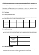
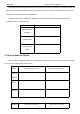
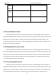


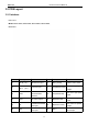
Table Of Contents
- Foreword
- Safety Notice
- CONTENTS
- Safety Notice on Maintenance
- Safety Notice on Operation
- 1. Product Introduction
- 2. Control
- 2.1 Operation Mode
- 2.2 Control Mode
- 2.3 Functions
- 2.3.1 Set Capacity Dial Code
- Set the capacity of the outdoor unit through the f
- Capacity
- 24K
- 36K
- 48K
- 60K
- Dial Codes
- 2.3.2 Set Defrost Mode
- The second digit dial code are selecting the defro
- 2.3.3 Set Operating Mode
- The third digit dial code and the fourth digit dia
- By setting the Forcible mode dial codes of the con
- Energy saving mode is achieved by setting the cond
- 2.3.4 Set Indoor Fan Speed
- Set the indoor fan speed through the four-digit di
- Capacity
- 24K indoor unit dial code
- 36K indoor unit dial code
- Level 1 (Default)
- Level 2
- Level 3
- Capacity
- 48K indoor unit dial code
- 60K indoor unit dial code
- Level 1 (Default)
- Level 2
- Level 3
- 2.3.5 Forced Defrost Control
- Press and hold "SW1" for about 5s to enter the fir
- 2.3.6 Refrigerant Recovery Control
- Press and hold "SW1" for about 5s to enter the fir
- 2.3.7 Forced Operation Control
- Press and hold "SW1" for about 5s to enter the fir
- 2.3.8 Thermostat Functions
- Thermostat model: XE70-00/E1, please refer to the
- 3.1 Wiring Diagrams
- 3.2 PCB Layout
- 3.2.2 IPM, PFC Testing Method
- 3.3 Error Code
- 3.4 Troubleshooting
- 3.4.1 “E1” Compressor High Pressure Protection
- 3.4.2 “E3” Compressor Low-pressure Protection, Ref
- 3.4.3 “E4” Compressor Air Discharge High-temperatu
- 3.4.4 “F2” Condenser Temperature Sensor Error
- 3.4.5 “F3” Outdoor Ambient Temperature Sensor Erro
- 3.4.6 “F4” Discharge Temperature Sensor Error
- 3.4.7 “F6” ODU Tube Temperature Sensor Error
- 3.4.8“EE” ODU Memory Chip Error
- 3.4.9 “H4” Overload
- 3.4.10 “H5” IPM Protection
- 3.4.11 “H6” DC Fan Error
- 3.4.12 “H7” Driver Out-of-Step Protection
- 3.4.13 “HC” PFC Protection
- 3.4.14 “Lc” Startup Failure
- 3.4.15 “P0” Driver Reset Protection
- 3.4.16 “P5” Over-Current Protection
- 3.4.17 “P6” Master Control and Driver Communicatio
- 3.4.18 “P7” Driver Module Sensor Error
- 3.4.19 “P8” Driver Module High Temperature Protec
- 3.4.20 “PA” AC Current Protection
- 3.4.21 “Pc” Driver Current Error
- 3.4.22 “PL” Bus Low-Voltage Protection
- 3.4.23 “PH” Bus High-Voltage Protection
- 3.4.24 “PU” Charge Loop Error
- 3.4.25 “ee” Drive Memory Chip Error
- 3.4.26 “e1” High Pressure Sensor Error
- 3.4.27 “C4” ODU Jumper Cap Error
- 3.5 Failures Not Caused by Errors
- 4. Maintenance
- Appendices
- 1. Resistance/Temperature Lists of Temperature Sen
- 2. Temperature/Pressure List of Refrigerant
- 3. Operation Tools

MRCOOL Universal Service Manual
8
2.2 Control Mode
2.2.1 Based Control
2.2.1.1 Compressor Control
When cooling or heating mode is turned on, indoor fan will run for a while before the compressor starts.
Under different modes, the compressor can only be stopped after running for some time (special cases excluded).
This is to protect the compressor from frequent start or stop. Once the compressor is stopped, it must not be
restarted right away. Please wait for a few minutes.
2.2.1.2 EXV Control
When the unit is first started, the electronic expansion valve will reset control. During the process, the
expansion valve will produce rattling sound. When cooling or heating mode is turned on, the valve will be open at
a certain step before the compressor starts.
2.2.1.3 Outdoor Fan Control
This series air conditioner has two types of outdoor units: one with a single fan and the other with double
fans. The outdoor fan can run at the highest level 10 and the lowest level 1. By controlling the speed of outdoor
fan, the unit can achieve cooling at low temperature and heating at high temperature. In fan mode, outdoor fan
will not work.
2.2.1.4 4-way Valve Control
After heating mode is turned on for a while, 4-way valve will be energized to change the direction of
refrigerant flow so that the system can run in heating and the indoor unit will not blow cold air. Under other modes,
the valve will not be energized.
To avoid the 4-way valve from incorrectly changing directions, when the unit stops in heating, due to a
temperature point or other protection reasons, the 4-way valve will continue to function temporarily and lose
power after a while.
There must be adequate differential pressure for the 4-way valve to change directions.
2.2.2 Special Control
2.2.2.1 Defrosting Control
ODU defrosting control in heating: Defrosting will start when the temperature sensed by outdoor tube
temperature sensor reaches a preset value. During defrosting, the 4-way valve will switch to the cooling condition,