
Troubleshooting Guide
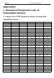
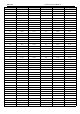
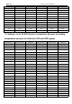
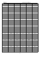
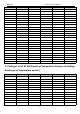


Table Of Contents
- Foreword
- Safety Notice
- CONTENTS
- Safety Notice on Maintenance
- Safety Notice on Operation
- 1. Product Introduction
- 2. Control
- 2.1 Operation Mode
- 2.2 Control Mode
- 2.3 Functions
- 2.3.1 Set Capacity Dial Code
- Set the capacity of the outdoor unit through the f
- Capacity
- 24K
- 36K
- 48K
- 60K
- Dial Codes
- 2.3.2 Set Defrost Mode
- The second digit dial code are selecting the defro
- 2.3.3 Set Operating Mode
- The third digit dial code and the fourth digit dia
- By setting the Forcible mode dial codes of the con
- Energy saving mode is achieved by setting the cond
- 2.3.4 Set Indoor Fan Speed
- Set the indoor fan speed through the four-digit di
- Capacity
- 24K indoor unit dial code
- 36K indoor unit dial code
- Level 1 (Default)
- Level 2
- Level 3
- Capacity
- 48K indoor unit dial code
- 60K indoor unit dial code
- Level 1 (Default)
- Level 2
- Level 3
- 2.3.5 Forced Defrost Control
- Press and hold "SW1" for about 5s to enter the fir
- 2.3.6 Refrigerant Recovery Control
- Press and hold "SW1" for about 5s to enter the fir
- 2.3.7 Forced Operation Control
- Press and hold "SW1" for about 5s to enter the fir
- 2.3.8 Thermostat Functions
- Thermostat model: XE70-00/E1, please refer to the
- 3.1 Wiring Diagrams
- 3.2 PCB Layout
- 3.2.2 IPM, PFC Testing Method
- 3.3 Error Code
- 3.4 Troubleshooting
- 3.4.1 “E1” Compressor High Pressure Protection
- 3.4.2 “E3” Compressor Low-pressure Protection, Ref
- 3.4.3 “E4” Compressor Air Discharge High-temperatu
- 3.4.4 “F2” Condenser Temperature Sensor Error
- 3.4.5 “F3” Outdoor Ambient Temperature Sensor Erro
- 3.4.6 “F4” Discharge Temperature Sensor Error
- 3.4.7 “F6” ODU Tube Temperature Sensor Error
- 3.4.8“EE” ODU Memory Chip Error
- 3.4.9 “H4” Overload
- 3.4.10 “H5” IPM Protection
- 3.4.11 “H6” DC Fan Error
- 3.4.12 “H7” Driver Out-of-Step Protection
- 3.4.13 “HC” PFC Protection
- 3.4.14 “Lc” Startup Failure
- 3.4.15 “P0” Driver Reset Protection
- 3.4.16 “P5” Over-Current Protection
- 3.4.17 “P6” Master Control and Driver Communicatio
- 3.4.18 “P7” Driver Module Sensor Error
- 3.4.19 “P8” Driver Module High Temperature Protec
- 3.4.20 “PA” AC Current Protection
- 3.4.21 “Pc” Driver Current Error
- 3.4.22 “PL” Bus Low-Voltage Protection
- 3.4.23 “PH” Bus High-Voltage Protection
- 3.4.24 “PU” Charge Loop Error
- 3.4.25 “ee” Drive Memory Chip Error
- 3.4.26 “e1” High Pressure Sensor Error
- 3.4.27 “C4” ODU Jumper Cap Error
- 3.5 Failures Not Caused by Errors
- 4. Maintenance
- Appendices
- 1. Resistance/Temperature Lists of Temperature Sen
- 2. Temperature/Pressure List of Refrigerant
- 3. Operation Tools

MRCOOL Universal Service Manual
115
Temperature (℃)
Resistance (kΩ)
Voltage (V)
Temperature (℃)
Resistance (kΩ)
Voltage (V)
27
45.074
0.599
118
2.0148
2.747
28
43.163
0.621
119
1.9626
2.759
29
41.313
0.643
120
1.9123
2.77
30
39.61
0.665
121
1.8652
2.781
31
37.958
0.688
122
1.8158
2.793
32
36.384
0.711
123
1.7698
2.804
33
34.883
0.735
124
1.7253
2.814
34
33.453
0.759
125
1.6821
2.825
35
32.088
0.784
126
1.6402
2.835
36
30.787
0.809
127
1.5996
2.845
37
29.544
0.835
128
1.5602
2.855
38
28.359
0.86
129
1.522
2.864
39
27.227
0.886
130
1.485
2.873
40
26.147
0.913
131
1.449
2.882
41
25.114
0.94
132
1.4141
2.891
42
24.128
0.967
133
1.3803
2.9
43
23.186
0.994
134
1.3474
2.908
44
22.286
1.022
135
1.3155
2.916
45
21.425
1.05
136
1.2846
2.924
46
20.601
1.078
137
1.2545
2.932
47
19.814
1.107
138
1.2233
2.94
48
19.061
1.136
139
1.1969
2.947
49
18.34
1.164
140
1.1694
2.955
50
17.651
1.193
141
1.1476
2.96
51
16.99
1.223
142
1.1166
2.969
52
16.358
1.252
143
1.0913
2.975
53
15.753
1.281
144
1.0667
2.982
54
15.173
1.311
145
1.0429
2.988
55
14.618
1.34
146
1.0197
2.995
56
14.085
1.37
147
0.9971
3.001
57
13.575
1.4
148
0.9752
3.007
58
13.086
1.429
149
0.9538
3.013
59
12.617
1.459
150
0.9331
3.018
60
12.368
1.475