
Troubleshooting Guide
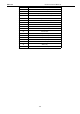
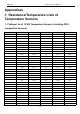
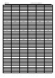
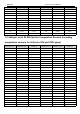
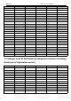


Table Of Contents
- Foreword
- Safety Notice
- CONTENTS
- Safety Notice on Maintenance
- Safety Notice on Operation
- 1. Product Introduction
- 2. Control
- 2.1 Operation Mode
- 2.2 Control Mode
- 2.3 Functions
- 2.3.1 Set Capacity Dial Code
- Set the capacity of the outdoor unit through the f
- Capacity
- 24K
- 36K
- 48K
- 60K
- Dial Codes
- 2.3.2 Set Defrost Mode
- The second digit dial code are selecting the defro
- 2.3.3 Set Operating Mode
- The third digit dial code and the fourth digit dia
- By setting the Forcible mode dial codes of the con
- Energy saving mode is achieved by setting the cond
- 2.3.4 Set Indoor Fan Speed
- Set the indoor fan speed through the four-digit di
- Capacity
- 24K indoor unit dial code
- 36K indoor unit dial code
- Level 1 (Default)
- Level 2
- Level 3
- Capacity
- 48K indoor unit dial code
- 60K indoor unit dial code
- Level 1 (Default)
- Level 2
- Level 3
- 2.3.5 Forced Defrost Control
- Press and hold "SW1" for about 5s to enter the fir
- 2.3.6 Refrigerant Recovery Control
- Press and hold "SW1" for about 5s to enter the fir
- 2.3.7 Forced Operation Control
- Press and hold "SW1" for about 5s to enter the fir
- 2.3.8 Thermostat Functions
- Thermostat model: XE70-00/E1, please refer to the
- 3.1 Wiring Diagrams
- 3.2 PCB Layout
- 3.2.2 IPM, PFC Testing Method
- 3.3 Error Code
- 3.4 Troubleshooting
- 3.4.1 “E1” Compressor High Pressure Protection
- 3.4.2 “E3” Compressor Low-pressure Protection, Ref
- 3.4.3 “E4” Compressor Air Discharge High-temperatu
- 3.4.4 “F2” Condenser Temperature Sensor Error
- 3.4.5 “F3” Outdoor Ambient Temperature Sensor Erro
- 3.4.6 “F4” Discharge Temperature Sensor Error
- 3.4.7 “F6” ODU Tube Temperature Sensor Error
- 3.4.8“EE” ODU Memory Chip Error
- 3.4.9 “H4” Overload
- 3.4.10 “H5” IPM Protection
- 3.4.11 “H6” DC Fan Error
- 3.4.12 “H7” Driver Out-of-Step Protection
- 3.4.13 “HC” PFC Protection
- 3.4.14 “Lc” Startup Failure
- 3.4.15 “P0” Driver Reset Protection
- 3.4.16 “P5” Over-Current Protection
- 3.4.17 “P6” Master Control and Driver Communicatio
- 3.4.18 “P7” Driver Module Sensor Error
- 3.4.19 “P8” Driver Module High Temperature Protec
- 3.4.20 “PA” AC Current Protection
- 3.4.21 “Pc” Driver Current Error
- 3.4.22 “PL” Bus Low-Voltage Protection
- 3.4.23 “PH” Bus High-Voltage Protection
- 3.4.24 “PU” Charge Loop Error
- 3.4.25 “ee” Drive Memory Chip Error
- 3.4.26 “e1” High Pressure Sensor Error
- 3.4.27 “C4” ODU Jumper Cap Error
- 3.5 Failures Not Caused by Errors
- 4. Maintenance
- Appendices
- 1. Resistance/Temperature Lists of Temperature Sen
- 2. Temperature/Pressure List of Refrigerant
- 3. Operation Tools

MRCOOL Universal Service Manual
116
2. Temperature/Pressure List of Refrigerant
R410A
Temperature
Pressure
Temperature
Pressure
Temperature
Pressure
℃
Kpa
℃
Kpa
℃
Kpa
-30
275
0
803
30
1880
-29
286
1
823
31
1910
-28
298
2
851
32
1960
-27
311
3
879
33
2030
-26
324
4
903
34
2080
-25
334
5
937
35
2130
-24
348
6
962
36
2180
-23
363
7
994
37
2240
-22
375
8
1020
38
2290
-21
391
9
1050
39
2350
-20
404
10
1090
40
2410
-19
424
11
1110
41
2460
-18
435
12
1150
42
2510
-17
453
13
1180
43
2580
-16
468
14
1220
44
2650
-15
483
15
1250
45
2710
-14
504
16
1280
46
2770
-13
520
17
1320
47
2840
-12
538
18
1350
48
2910
-11
556
19
1400
49
2980
-10
579
20
1440
50
3050
-9
598
21
1470
51
3100
-8
618
22
1520
52
3180
-7
639
23
1560
53
3250
-6
660
24
1600
54
3320
-5
682
25
1640
55
3400
-4
705
26
1680
56
3480
-3
728
27
1730
57
3540
-2
752
28
1780
58
3630
-1
777
29
1820
59
3720
3. Operation Tools
The following tools will be used: 1) Liquid-level gauge; 2) Screwdriver; 3) Electric driven rotary hammer; 4) Drill; 5) Pipe expander; 6)
Torque wrench; 7) Open-end wrench; 8) Pipe cutter; 9) Leak detector; 10) Vacuum pump; 11) Pressure gauge; 12) Universal meter;
13) Hexagon wrench; 14) Tapeline.