
Troubleshooting Guide
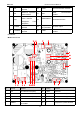

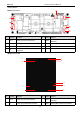

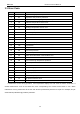
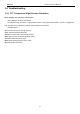
Table Of Contents
- Foreword
- Safety Notice
- CONTENTS
- Safety Notice on Maintenance
- Safety Notice on Operation
- 1. Product Introduction
- 2. Control
- 2.1 Operation Mode
- 2.2 Control Mode
- 2.3 Functions
- 2.3.1 Set Capacity Dial Code
- Set the capacity of the outdoor unit through the f
- Capacity
- 24K
- 36K
- 48K
- 60K
- Dial Codes
- 2.3.2 Set Defrost Mode
- The second digit dial code are selecting the defro
- 2.3.3 Set Operating Mode
- The third digit dial code and the fourth digit dia
- By setting the Forcible mode dial codes of the con
- Energy saving mode is achieved by setting the cond
- 2.3.4 Set Indoor Fan Speed
- Set the indoor fan speed through the four-digit di
- Capacity
- 24K indoor unit dial code
- 36K indoor unit dial code
- Level 1 (Default)
- Level 2
- Level 3
- Capacity
- 48K indoor unit dial code
- 60K indoor unit dial code
- Level 1 (Default)
- Level 2
- Level 3
- 2.3.5 Forced Defrost Control
- Press and hold "SW1" for about 5s to enter the fir
- 2.3.6 Refrigerant Recovery Control
- Press and hold "SW1" for about 5s to enter the fir
- 2.3.7 Forced Operation Control
- Press and hold "SW1" for about 5s to enter the fir
- 2.3.8 Thermostat Functions
- Thermostat model: XE70-00/E1, please refer to the
- 3.1 Wiring Diagrams
- 3.2 PCB Layout
- 3.2.2 IPM, PFC Testing Method
- 3.3 Error Code
- 3.4 Troubleshooting
- 3.4.1 “E1” Compressor High Pressure Protection
- 3.4.2 “E3” Compressor Low-pressure Protection, Ref
- 3.4.3 “E4” Compressor Air Discharge High-temperatu
- 3.4.4 “F2” Condenser Temperature Sensor Error
- 3.4.5 “F3” Outdoor Ambient Temperature Sensor Erro
- 3.4.6 “F4” Discharge Temperature Sensor Error
- 3.4.7 “F6” ODU Tube Temperature Sensor Error
- 3.4.8“EE” ODU Memory Chip Error
- 3.4.9 “H4” Overload
- 3.4.10 “H5” IPM Protection
- 3.4.11 “H6” DC Fan Error
- 3.4.12 “H7” Driver Out-of-Step Protection
- 3.4.13 “HC” PFC Protection
- 3.4.14 “Lc” Startup Failure
- 3.4.15 “P0” Driver Reset Protection
- 3.4.16 “P5” Over-Current Protection
- 3.4.17 “P6” Master Control and Driver Communicatio
- 3.4.18 “P7” Driver Module Sensor Error
- 3.4.19 “P8” Driver Module High Temperature Protec
- 3.4.20 “PA” AC Current Protection
- 3.4.21 “Pc” Driver Current Error
- 3.4.22 “PL” Bus Low-Voltage Protection
- 3.4.23 “PH” Bus High-Voltage Protection
- 3.4.24 “PU” Charge Loop Error
- 3.4.25 “ee” Drive Memory Chip Error
- 3.4.26 “e1” High Pressure Sensor Error
- 3.4.27 “C4” ODU Jumper Cap Error
- 3.5 Failures Not Caused by Errors
- 4. Maintenance
- Appendices
- 1. Resistance/Temperature Lists of Temperature Sen
- 2. Temperature/Pressure List of Refrigerant
- 3. Operation Tools

MRCOOL Universal Service Manual
23
3
E
Filtering board ground wire terminal
8
L-OUT1
Power output live wire terminal
4
E1
Filtering board grounding hole
(reserved)
9
L-OUT
Power output live wire terminal
5
DC-BUS
Power discharge terminal (for testing)
3.2.2 IPM, PFC Testing Method
3.2.2.1Method of Testing IPM Module
(1) Preparation before test: prepare a universal meter and turn to its diode option, and then remove the wires U,
V, W of the compressor after it is powered off for one minute.
(2) Testing Steps
Step 1: put the black probe on the place P and the red one on the wiring terminal U, V, W respectively as
shown in the following figure to measure the voltage between UP, VP and WP.
Step 2: put the red probe on the place N and the black one on the wiring terminal U, V, W respectively as
shown in the following figure to measure the voltage between NU, NV and NW.
(3) If the measured voltages between UP, VP, WP, NU, NV, NV are all among 0.3V-0.7V, then it indicates the
IPM module is normal; If any measured valve is 0, it indicates the IPM is damaged.
3.2.2.2 Method of Testing PFC Module Short Circuit
(1) Preparation before test: prepare a universal meter and turn to its diode option, and then remove the wires
L1-2, L2-1 after it is powered off for one minute.
(2) Testing Steps:
Step 1: Put the black probe on the place P and the red one on the wiring terminal L1-2, L2-1 respectively as
shown in the following figure to measure the voltage between L1-2 and P; L2-1 and P.
Step 2: Put the red probe on the place N and the black one on the wiring terminal L1-2, L2-1 respectively as
shown in the following figure to measure the voltage between N and L1-2; N and L2-1.
(3) If the measured voltages between L1-2 and P; L2-1 and P; N and L1-2; N and L2-1 are all among 0.3V-0.7V,
then it indicates the PFC module is normal; If any measured valve is 0, it indicates the PFC is damaged.
MDUO1836