
Troubleshooting Guide
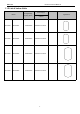
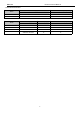
Table Of Contents
- Foreword
- Safety Notice
- CONTENTS
- Safety Notice on Maintenance
- Safety Notice on Operation
- 1. Product Introduction
- 2. Control
- 2.1 Operation Mode
- 2.2 Control Mode
- 2.3 Functions
- 2.3.1 Set Capacity Dial Code
- Set the capacity of the outdoor unit through the f
- Capacity
- 24K
- 36K
- 48K
- 60K
- Dial Codes
- 2.3.2 Set Defrost Mode
- The second digit dial code are selecting the defro
- 2.3.3 Set Operating Mode
- The third digit dial code and the fourth digit dia
- By setting the Forcible mode dial codes of the con
- Energy saving mode is achieved by setting the cond
- 2.3.4 Set Indoor Fan Speed
- Set the indoor fan speed through the four-digit di
- Capacity
- 24K indoor unit dial code
- 36K indoor unit dial code
- Level 1 (Default)
- Level 2
- Level 3
- Capacity
- 48K indoor unit dial code
- 60K indoor unit dial code
- Level 1 (Default)
- Level 2
- Level 3
- 2.3.5 Forced Defrost Control
- Press and hold "SW1" for about 5s to enter the fir
- 2.3.6 Refrigerant Recovery Control
- Press and hold "SW1" for about 5s to enter the fir
- 2.3.7 Forced Operation Control
- Press and hold "SW1" for about 5s to enter the fir
- 2.3.8 Thermostat Functions
- Thermostat model: XE70-00/E1, please refer to the
- 3.1 Wiring Diagrams
- 3.2 PCB Layout
- 3.2.2 IPM, PFC Testing Method
- 3.3 Error Code
- 3.4 Troubleshooting
- 3.4.1 “E1” Compressor High Pressure Protection
- 3.4.2 “E3” Compressor Low-pressure Protection, Ref
- 3.4.3 “E4” Compressor Air Discharge High-temperatu
- 3.4.4 “F2” Condenser Temperature Sensor Error
- 3.4.5 “F3” Outdoor Ambient Temperature Sensor Erro
- 3.4.6 “F4” Discharge Temperature Sensor Error
- 3.4.7 “F6” ODU Tube Temperature Sensor Error
- 3.4.8“EE” ODU Memory Chip Error
- 3.4.9 “H4” Overload
- 3.4.10 “H5” IPM Protection
- 3.4.11 “H6” DC Fan Error
- 3.4.12 “H7” Driver Out-of-Step Protection
- 3.4.13 “HC” PFC Protection
- 3.4.14 “Lc” Startup Failure
- 3.4.15 “P0” Driver Reset Protection
- 3.4.16 “P5” Over-Current Protection
- 3.4.17 “P6” Master Control and Driver Communicatio
- 3.4.18 “P7” Driver Module Sensor Error
- 3.4.19 “P8” Driver Module High Temperature Protec
- 3.4.20 “PA” AC Current Protection
- 3.4.21 “Pc” Driver Current Error
- 3.4.22 “PL” Bus Low-Voltage Protection
- 3.4.23 “PH” Bus High-Voltage Protection
- 3.4.24 “PU” Charge Loop Error
- 3.4.25 “ee” Drive Memory Chip Error
- 3.4.26 “e1” High Pressure Sensor Error
- 3.4.27 “C4” ODU Jumper Cap Error
- 3.5 Failures Not Caused by Errors
- 4. Maintenance
- Appendices
- 1. Resistance/Temperature Lists of Temperature Sen
- 2. Temperature/Pressure List of Refrigerant
- 3. Operation Tools
CONTENTS
Safety Notice on Maintenance
..................................................................................................................
1
Safety Notice on Operation
........................................................................................................................
2
1. Product Introduction
...............................................................................................................................
3
1.1 Lists of Units......................................................................................................................................................... 3
1.2 Electrical Parameters.......................................................................................................................................... 5
2. Control
........................................................................................................................................................
6
2.1 Operation Mode....................................................................................................................................................6
2.2 Control Mode........................................................................................................................................................ 8
2.3 Functions
.............................................................................................................................................................
10
3. Troubleshooting
.....................................................................................................................................
14
3.1 Wiring Diagrams.................................................................................................................................................14
3.2 PCB Layout
.........................................................................................................................
...............................17
3.3 Error Code...........................................................................................................................................................26
3.4 Troubleshooting
..................................................................................................................
..............................27
3.5 Failures Not Caused by Errors........................................................................................................................ 27
4. Maintenance
............................................................................................................................................
55
4.1 System Diagram.................................................................................................................................................55
4.2 Connection Pipe Vacuum Pumping................................................................................................................ 55
4.3 Refrigerant Charging.........................................................................................................................................57
4.4 Maintenance of Major Components................................................................................................................59
4.5 Removal of Major Components.......................................................................................................................69
4.6 Explosive View and Lists of Parts................................................................................................................. 103
Appendices
................................................................................................................................................
109
1. Resistance/Temperature Lists of Temperature Sensors
...........................................................
109
1.1 Voltage List of 15 kΩ Temperature Sensors (including ODU and IDU temperature sensors).............109
1.2 Voltage List of 20 kΩ Pipeline Temperature Sensors (including temperature sensors for defroster, IDU
and ODU pipes)...................................................................................................................................................... 111
1.3 Voltage List of 50 kΩ Discharge Temperature Sensors (including discharge air temperature sensor)
...................................................................................................................................................................................113
2. Temperature/Pressure List of Refrigerant
.....................................................................................
116
3. Refrigerant Notice/Concentration
...................................................................................................
116
4. Operation Tools
....................................................................................................................................
116