
Troubleshooting Guide
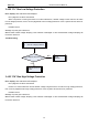

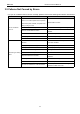
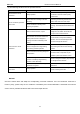


Table Of Contents
- Foreword
- Safety Notice
- CONTENTS
- Safety Notice on Maintenance
- Safety Notice on Operation
- 1. Product Introduction
- 2. Control
- 2.1 Operation Mode
- 2.2 Control Mode
- 2.3 Functions
- 2.3.1 Set Capacity Dial Code
- Set the capacity of the outdoor unit through the f
- Capacity
- 24K
- 36K
- 48K
- 60K
- Dial Codes
- 2.3.2 Set Defrost Mode
- The second digit dial code are selecting the defro
- 2.3.3 Set Operating Mode
- The third digit dial code and the fourth digit dia
- By setting the Forcible mode dial codes of the con
- Energy saving mode is achieved by setting the cond
- 2.3.4 Set Indoor Fan Speed
- Set the indoor fan speed through the four-digit di
- Capacity
- 24K indoor unit dial code
- 36K indoor unit dial code
- Level 1 (Default)
- Level 2
- Level 3
- Capacity
- 48K indoor unit dial code
- 60K indoor unit dial code
- Level 1 (Default)
- Level 2
- Level 3
- 2.3.5 Forced Defrost Control
- Press and hold "SW1" for about 5s to enter the fir
- 2.3.6 Refrigerant Recovery Control
- Press and hold "SW1" for about 5s to enter the fir
- 2.3.7 Forced Operation Control
- Press and hold "SW1" for about 5s to enter the fir
- 2.3.8 Thermostat Functions
- Thermostat model: XE70-00/E1, please refer to the
- 3.1 Wiring Diagrams
- 3.2 PCB Layout
- 3.2.2 IPM, PFC Testing Method
- 3.3 Error Code
- 3.4 Troubleshooting
- 3.4.1 “E1” Compressor High Pressure Protection
- 3.4.2 “E3” Compressor Low-pressure Protection, Ref
- 3.4.3 “E4” Compressor Air Discharge High-temperatu
- 3.4.4 “F2” Condenser Temperature Sensor Error
- 3.4.5 “F3” Outdoor Ambient Temperature Sensor Erro
- 3.4.6 “F4” Discharge Temperature Sensor Error
- 3.4.7 “F6” ODU Tube Temperature Sensor Error
- 3.4.8“EE” ODU Memory Chip Error
- 3.4.9 “H4” Overload
- 3.4.10 “H5” IPM Protection
- 3.4.11 “H6” DC Fan Error
- 3.4.12 “H7” Driver Out-of-Step Protection
- 3.4.13 “HC” PFC Protection
- 3.4.14 “Lc” Startup Failure
- 3.4.15 “P0” Driver Reset Protection
- 3.4.16 “P5” Over-Current Protection
- 3.4.17 “P6” Master Control and Driver Communicatio
- 3.4.18 “P7” Driver Module Sensor Error
- 3.4.19 “P8” Driver Module High Temperature Protec
- 3.4.20 “PA” AC Current Protection
- 3.4.21 “Pc” Driver Current Error
- 3.4.22 “PL” Bus Low-Voltage Protection
- 3.4.23 “PH” Bus High-Voltage Protection
- 3.4.24 “PU” Charge Loop Error
- 3.4.25 “ee” Drive Memory Chip Error
- 3.4.26 “e1” High Pressure Sensor Error
- 3.4.27 “C4” ODU Jumper Cap Error
- 3.5 Failures Not Caused by Errors
- 4. Maintenance
- Appendices
- 1. Resistance/Temperature Lists of Temperature Sen
- 2. Temperature/Pressure List of Refrigerant
- 3. Operation Tools

MRCOOL Universal Service Manual
55
4. Maintenance
4.1 System Diagram
CompressorCompressor
EvaporatorEvaporator
AccumulatorAccumulator
ElectromagneticElectromagnetic ValveValve
Gas-liquidGas-liquid separatorseparator
4-Way4-Way ValveValve
CondensorCondensor
PressurePressure SensorSensor
HighHigh PressurePressure SwitchSwitch
FirstFirst levellevel EXVEXV
OneOne WayWay ValveValve
ThermalThermal ExpansionExpansion ValveValve
CoolingCooling
HeatingHeating
SecondSecond levellevel EXVEXV
LowLow PressurePressure SwitchSwitch
4.2 Connection Pipe Vacuum Pumping
NOTICE
1
Make sure the outlet of vacuum pump is away from fire source and is well-ventilated.
2
Before vacuum pumping, make sure the unit cut-off valves are closed.
3
When vacuum pumping, both the liquid pipe and the gas pipe must be pumped.
(1) Remove the caps of the liquid valve, gas valve and also the service port.
(2) meanwhile the gas and liquid valves should be kept closed in case of refrigerant leak.
(3) Connect the hose used for evacuation to the vacuum pump.
(4) Open the switch at the lower pressure side of the manifold valve assembly and start the vacuum pump.
Meanwhile, the switch at the high pressure side of the manifold valve assembly should be kept closed,
otherwise evacuation would fail.
(5) The evacuation duration depends on the unit’s capacity, generally.
Model
Time(min)
MDUO1836
35
MDUO1860
40
And verify if the pressure gauge at the low pressure side of the manifold valve assembly reads -1.0Mpa
(-750mmHg), if not, it indicates there is leak somewhere. Then, close the switch fully and then stop the vacuum
pump.