
Troubleshooting Guide
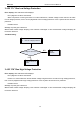
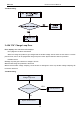
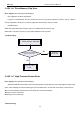
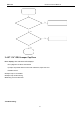

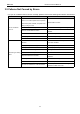
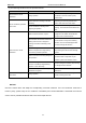


Table Of Contents
- Foreword
- Safety Notice
- CONTENTS
- Safety Notice on Maintenance
- Safety Notice on Operation
- 1. Product Introduction
- 2. Control
- 2.1 Operation Mode
- 2.2 Control Mode
- 2.3 Functions
- 2.3.1 Set Capacity Dial Code
- Set the capacity of the outdoor unit through the f
- Capacity
- 24K
- 36K
- 48K
- 60K
- Dial Codes
- 2.3.2 Set Defrost Mode
- The second digit dial code are selecting the defro
- 2.3.3 Set Operating Mode
- The third digit dial code and the fourth digit dia
- By setting the Forcible mode dial codes of the con
- Energy saving mode is achieved by setting the cond
- 2.3.4 Set Indoor Fan Speed
- Set the indoor fan speed through the four-digit di
- Capacity
- 24K indoor unit dial code
- 36K indoor unit dial code
- Level 1 (Default)
- Level 2
- Level 3
- Capacity
- 48K indoor unit dial code
- 60K indoor unit dial code
- Level 1 (Default)
- Level 2
- Level 3
- 2.3.5 Forced Defrost Control
- Press and hold "SW1" for about 5s to enter the fir
- 2.3.6 Refrigerant Recovery Control
- Press and hold "SW1" for about 5s to enter the fir
- 2.3.7 Forced Operation Control
- Press and hold "SW1" for about 5s to enter the fir
- 2.3.8 Thermostat Functions
- Thermostat model: XE70-00/E1, please refer to the
- 3.1 Wiring Diagrams
- 3.2 PCB Layout
- 3.2.2 IPM, PFC Testing Method
- 3.3 Error Code
- 3.4 Troubleshooting
- 3.4.1 “E1” Compressor High Pressure Protection
- 3.4.2 “E3” Compressor Low-pressure Protection, Ref
- 3.4.3 “E4” Compressor Air Discharge High-temperatu
- 3.4.4 “F2” Condenser Temperature Sensor Error
- 3.4.5 “F3” Outdoor Ambient Temperature Sensor Erro
- 3.4.6 “F4” Discharge Temperature Sensor Error
- 3.4.7 “F6” ODU Tube Temperature Sensor Error
- 3.4.8“EE” ODU Memory Chip Error
- 3.4.9 “H4” Overload
- 3.4.10 “H5” IPM Protection
- 3.4.11 “H6” DC Fan Error
- 3.4.12 “H7” Driver Out-of-Step Protection
- 3.4.13 “HC” PFC Protection
- 3.4.14 “Lc” Startup Failure
- 3.4.15 “P0” Driver Reset Protection
- 3.4.16 “P5” Over-Current Protection
- 3.4.17 “P6” Master Control and Driver Communicatio
- 3.4.18 “P7” Driver Module Sensor Error
- 3.4.19 “P8” Driver Module High Temperature Protec
- 3.4.20 “PA” AC Current Protection
- 3.4.21 “Pc” Driver Current Error
- 3.4.22 “PL” Bus Low-Voltage Protection
- 3.4.23 “PH” Bus High-Voltage Protection
- 3.4.24 “PU” Charge Loop Error
- 3.4.25 “ee” Drive Memory Chip Error
- 3.4.26 “e1” High Pressure Sensor Error
- 3.4.27 “C4” ODU Jumper Cap Error
- 3.5 Failures Not Caused by Errors
- 4. Maintenance
- Appendices
- 1. Resistance/Temperature Lists of Temperature Sen
- 2. Temperature/Pressure List of Refrigerant
- 3. Operation Tools

MRCOOL Universal Service Manual
56
(6) Wait for 10min to see if the system pressure can remain unchanged. If the pressure increase, there may be
leakage.
(7) Slightly open the liquid valve and let some refrigerant go to the connection pipe to balance the pressure
inside and outside of the connection pipe, so that air will not come into the connection pipe when removing
the hose. Notice that the gas and liquid valve can be opened fully only after the manifold valve assembly is
removed.
(8) Place back the caps of the liquid valve, gas valve and also the service port.
NOTICE:
For large-size units, there are maintenance ports for liquid valve and gas valve. During evacuation, you may
connect the two hoses of the branch valve assembly to the maintenance ports to speed up the evacuation.
Refrigerant should be reclaimed into the appropriate storage tank. System should use oxygen-free nitrogen
purging to ensure safety. This process may need to repeat several times. Do not use compressed air or oxygen in
this process.