
Troubleshooting Guide
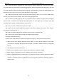


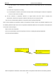


Table Of Contents
- Foreword
- Safety Notice
- CONTENTS
- Safety Notice on Maintenance
- Safety Notice on Operation
- 1. Product Introduction
- 2. Control
- 2.1 Operation Mode
- 2.2 Control Mode
- 2.3 Functions
- 2.3.1 Set Capacity Dial Code
- Set the capacity of the outdoor unit through the f
- Capacity
- 24K
- 36K
- 48K
- 60K
- Dial Codes
- 2.3.2 Set Defrost Mode
- The second digit dial code are selecting the defro
- 2.3.3 Set Operating Mode
- The third digit dial code and the fourth digit dia
- By setting the Forcible mode dial codes of the con
- Energy saving mode is achieved by setting the cond
- 2.3.4 Set Indoor Fan Speed
- Set the indoor fan speed through the four-digit di
- Capacity
- 24K indoor unit dial code
- 36K indoor unit dial code
- Level 1 (Default)
- Level 2
- Level 3
- Capacity
- 48K indoor unit dial code
- 60K indoor unit dial code
- Level 1 (Default)
- Level 2
- Level 3
- 2.3.5 Forced Defrost Control
- Press and hold "SW1" for about 5s to enter the fir
- 2.3.6 Refrigerant Recovery Control
- Press and hold "SW1" for about 5s to enter the fir
- 2.3.7 Forced Operation Control
- Press and hold "SW1" for about 5s to enter the fir
- 2.3.8 Thermostat Functions
- Thermostat model: XE70-00/E1, please refer to the
- 3.1 Wiring Diagrams
- 3.2 PCB Layout
- 3.2.2 IPM, PFC Testing Method
- 3.3 Error Code
- 3.4 Troubleshooting
- 3.4.1 “E1” Compressor High Pressure Protection
- 3.4.2 “E3” Compressor Low-pressure Protection, Ref
- 3.4.3 “E4” Compressor Air Discharge High-temperatu
- 3.4.4 “F2” Condenser Temperature Sensor Error
- 3.4.5 “F3” Outdoor Ambient Temperature Sensor Erro
- 3.4.6 “F4” Discharge Temperature Sensor Error
- 3.4.7 “F6” ODU Tube Temperature Sensor Error
- 3.4.8“EE” ODU Memory Chip Error
- 3.4.9 “H4” Overload
- 3.4.10 “H5” IPM Protection
- 3.4.11 “H6” DC Fan Error
- 3.4.12 “H7” Driver Out-of-Step Protection
- 3.4.13 “HC” PFC Protection
- 3.4.14 “Lc” Startup Failure
- 3.4.15 “P0” Driver Reset Protection
- 3.4.16 “P5” Over-Current Protection
- 3.4.17 “P6” Master Control and Driver Communicatio
- 3.4.18 “P7” Driver Module Sensor Error
- 3.4.19 “P8” Driver Module High Temperature Protec
- 3.4.20 “PA” AC Current Protection
- 3.4.21 “Pc” Driver Current Error
- 3.4.22 “PL” Bus Low-Voltage Protection
- 3.4.23 “PH” Bus High-Voltage Protection
- 3.4.24 “PU” Charge Loop Error
- 3.4.25 “ee” Drive Memory Chip Error
- 3.4.26 “e1” High Pressure Sensor Error
- 3.4.27 “C4” ODU Jumper Cap Error
- 3.5 Failures Not Caused by Errors
- 4. Maintenance
- Appendices
- 1. Resistance/Temperature Lists of Temperature Sen
- 2. Temperature/Pressure List of Refrigerant
- 3. Operation Tools

MRCOOL Universal Service Manual
67
pressure above 25kgf. Close the big and small valves and keep the pressure of indoor and outdoor units
for more than 12h. If the pressure remains unchanged, then start vacuum pumping; otherwise, check
the system for leaks again.
Temperature should be considered when judging the pressure change. If temperature changes by 1
℃
,
pressure will change by 0.01MPa or so.
For example, if temperature is 30
℃
when nitrogen of 2.5MPa is charged, and temperature changes to 25
℃
after 12h, we consider that the system is qualified if the pressure is found at 2.43MPa or above.
Step 11: Evacuate the system and charge refrigerant
Please refer to the section of maintenance: vacuum pumping and refrigerant charging.
Step 12: Connect electric components
Connect cables, compressor wires and the electric heating belt according to the signs marked before and
the wiring diagram on the cover of the electric box.
4.4.3 How to replace the drive module of compressor
Step 1: First, make sure that power is cut off. Set the universal meter at the AC voltage and measure the
voltage between L1, L2, L3, and N. If each time the voltage is 0V (Errors may occur to the universal meter,
sometimes the voltage may not be 0V), proceed with the next step and put a sign on the power switch that reads
“Under maintenance, don’t switch on”.
Step 2: Measure the voltage between DC bus P and N on the drive board of the compressor. Set the
universal meter at the DC voltage and measure the voltage between P and N as shown below. If the voltage is
below 36V, proceed with the next step. In case that a universal meter is not available, disconnect power for 20min
and then continue with the next step.
Step 3: Remove all the wires on the drive board of the compressor.