
Use and Care Manual
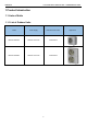
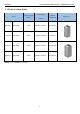
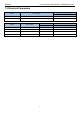
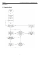
Table Of Contents
- Foreword
- Safety Notice
- CONTENTS
- Safety Notice on Maintenance
- Safety Notice on Operation
- 1 Product Introduction
- NOTE: 1 Ton =12000Btu/h = 3.517kW 1.2 Electrical Parameters
- 2 Control
- 3 Troubleshooting
- 3.1 Wiring Diagrams
- 3.2 PCB Layout
- 3.3 Error Code
- 3.4 Troubleshooting
- 3.4.1 “E1” Compressor High Pressure Protection
- 3.4.2 “E3” Compressor Low-pressure Protection, Refrigerant Shortage Protection, Refrigerant Recovery Mode
- 3.4.3 “E4” Compressor Air Discharge High-temperature Protection
- 3.4.4 “F2” Condenser Temperature Sensor Error
- 3.4.5 “F3” Outdoor Ambient Temperature Sensor Error
- 3.4.6 “F4” Discharge Temperature Sensor Error
- 3.4.7 “F6” ODU Tube Temperature Sensor Error
- 3.4.8“EE” ODU Memory Chip Error
- 3.4.9 “H4” Overload
- 3.4.10 “H5” IPM Protection
- 3.4.11 “H6” DC Fan Error
- 3.4.12 “H7” Driver Out-of-Step Protection
- 3.4.13 “HC” PFC Protection
- 3.4.14 “Lc” Startup Failure
- 3.4.15 “P0” Driver Reset Protection
- 3.4.16 “P5” Over-Current Protection
- 3.4.17 “P6” Master Control and Driver Communication Error
- 3.4.18 “P7” Driver Module Sensor Error
- 3.4.19 “P8” Driver Module High Temperature Protection
- 3.4.20 “PA” AC Current Protection
- 3.4.21 “Pc” Driver Current Error
- 3.4.22 “PL” Bus Low-Voltage Protection
- 3.4.23 “PH” Bus High-Voltage Protection
- 3.4.24 “PU” Charge Loop Error
- 3.4.25 “ee” Drive Memory Chip Error
- 3.5 Failures Not Caused by Errors
- 4 Maintenance
- Appendices
- 1 Resistance/Temperature Lists of Temperature Sensors
- 1.1 Voltage List of 15 KΩ Temperature Sensors (including ODU temperature sensors)
- 1.2 Voltage List of 20 KΩ Pipeline Temperature Sensors (including temperature sensors for defroster, IDU and ODU pipes)
- 1.3 Voltage List of 50 KΩ Discharge Temperature Sensors (including discharge air temperature sensor)
- 2 Temperature/Pressure List of Refrigerant
- 3 Operation Tools

CONTENTS
1 Product Introduction ...................................................................................................... 3
1.1 Lists of Units .......................................................................................................................... 3
1.2 Electrical Parameters ............................................................................................................. 5
2 Control ............................................................................................................................. 6
2.1 Operation Mode ..................................................................................................................... 6
2.2 Control Mode ......................................................................................................................... 7
2.3 Functions ............................................................................................................................... 8
3 Troubleshooting ............................................................................................................ 12
3.1 Wiring Diagrams .................................................................................................................. 12
3.2 PCB Layout .......................................................................................................................... 15
3.3 Error Code ........................................................................................................................... 22
3.4 Troubleshooting ................................................................................................................... 23
3.5 Failures Not Caused by Errors ............................................................................................. 48
4 Maintenance .................................................................................................................. 50
4.1 System Diagram .................................................................................................................. 50
4.2 Connection Pipe Vacuum Pumping ...................................................................................... 50
4.3 Refrigerant Charging ............................................................................................................ 52
4.4 Maintenance of Major Components ...................................................................................... 54
4.5 Removal of Major Components ............................................................................................ 62
4.6 Explosive View and Lists of Parts ......................................................................................... 84
Appendices ...................................................................................................................... 91
1 Resistance/Temperature Lists of Temperature Sensors ........................................... 91
1.1 Voltage List of 15 KΩ Temperature Sensors ......................................................................... 91
1.2 Voltage List of 20 KΩ Pipeline Temperature Sensors ........................................................... 93
1.3 Voltage List of 50 KΩ Discharge Temperature Sensors ........................................................ 95
2 Temperature/Pressure List of Refrigerant .................................................................. 98
3 Operation Tools ............................................................................................................ 98