
Use and Care Manual


507277-03CPage 24 of 53 mrcool.com
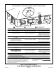
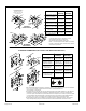
* Use wall support every 24” (610 mm). Use two
wall supports if extension is greater than
24” (610 mm) but less than 48” (1219 mm).
NOTE − One wall support must be within 6” (152 mm)
from top of each pipe (intake and exhaust) to prevent
movement in any direction.
NOTE − FIELD−PROVIDED
REDUCER MAY BE
REQUIRED TOADAPT
LARGER VENT PIPE SIZE
TO TERMINATION
STRAIGHT
APPPLICATION
EXTENDED
APPLICATION
D
B
D
B
A
2” (51mm)
Vent Pipe
3” (76mm)
Vent Pipe
A− Minimum clearance
above grade or average
snow accumulation
B− Maximum horizontal
separation between
intake and exhaust
D− Maximum exhaust
pipe length
E− Maximum wall support
distance from top of each
pipe (intake/exhaust)
12” (305 mm)
12” (305 mm)
12” (305 mm)
6” (152 mm)6” (152 mm)
6” (152 mm)6” (152 mm)
8” (203 mm)8” (203 mm)
20” (508 mm)
6” (152 mm)6” (152 mm)
A
Intake
Elbow
* WALL
SUPPORT
B
A
D
E
B
D
E
A
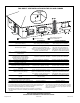
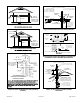
ALTERNATE TERMINATIONS (TEE & FORTY−FIVE DEGREE ELBOWS ONLY)
C2 -Minimum from end of
exhaust to inlet of intake
C1 -Minimum from end of
exhaust to inlet of intake
FIELD FABRICATED WALL TERMINATION
C1
C2
C1
C2
Front View of
Intake and Exhaust
Intake
Exhaust
C
B
1
2
D
A
C
3
Intake
Elbow
Exhaust
B
A
D
2” (51MM)
Vent Pipe
3” (76MM)
Vent Pipe
A− Clearance above
grade or average snow
accumulation
B− Horizontal
separation between
intake and exhaust
C− Minimum from
end of exhaust to
inlet of intake
D− Exhaust pipe length
E− Wall support distance
from top of each pipe
(intake/exhaust)
12” (305 mm) Min. 12” (305 mm) Min.
6” (152 mm) Min.
24” (610 mm) Max.
9” (227 mm) Min.
12” (305 mm) Min.
16” (405 mm) Max.
6” (152 mm) Max.
6” (152 mm) Min.
24” (610 mm) Max.
9” (227 mm) Min.
12” (305 mm) Min.
20” (508 mm) Max.
6” (152 mm) Max.
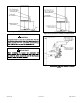
D
C
12”
1
2
E
B
A
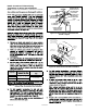
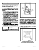
1
The exhaust termination tee should be connected to the 2” or 3” PVC flue pipe as shown in the illustration.
Do not use an accelerator in applications that include an exhaust termination tee.
The accelerator is not required.
2
As required. Flue gas may be acidic and may adversely affect some building materials. If a side wall vent
termination is used and flue gases will impinge on the building materials, a corrosion-resistant shield
(24 inches square) should be used to protect the wall surface. If optional tee is used, the protective shield
is recommended. The shield should be constructed using wood, sheet metal or other suitable material.
All seams, joints, cracks, etc. in affected area, should be sealed using an appropriate sealant.
3
Exhaust pipe 45° elbow can be rotated to the side away from the combustion air inlet to direct exhaust
away from adjacent property. The exhaust must never be directed toward the combustion air inlet.
D
C
12”
1
2
E
B
A
Figure 31.