The Signature Series is NOT designed for amateur installation. Installation SHOULD be performed by an authorized technician. Please read this manual carefully before installation and keep it for future reference. Owner & Installation Manual Signature Series MGD*95SE*XA Gas Furnace The Signature Series is NOT designed for amateur installation. Installation SHOULD be performed by an authorized technician. Please read this manual carefully before installation and keep it for future reference.
INSTALLATION INSTRUCTIONS MGD*95SE*XA Warm Air Gas Furnace This manual must be left with the homeowner for future reference. Table of Contents Unit Dimensions Parts Arrangement Gas Furnace 2 3 4 4 4 6 6 9 12 12 14 Safety Information Duct System 28 31 34 37 41 42 43 44 46 52 WARNING CAUTION *P507277-03C* Manufactured By MRCOOL,LLC Hickory, KY 42051 (P) 507277-03C Save these instructions for future reference 507277-03C mrcool.
Unit Dimensions 9/16 (14) COMBUSTION AIR INTAKE Return Air Opening B EXHAUST AIR OUTLET 2 1/16 (52) 5 (127) 2 1/4 (57) TOP VIEW 27 3/4 (705) 1 (25) Front Panel AIR 19 7/16 (494) 9/16 (14) FLOW 9/16 (14) ELECTRICAL INLET (Either Side) 33 (838) 2 (51) Either Side CONDENSATE TRAP CONNECTION (Either Side) GAS PIPING INLET (Either Side) 9 1/8 (232) Right 6 9/16 (167) Left 3/4 (19) C 3/4 (19) Supply Air Capacity 9 (229) 6 1/2 (165) Either Side 19 1/4 Supply (489) Air FRONT VIEW Page 2
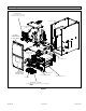
Parts Arrangement CONTROLBOX (Includesintegratedcontrol, transformer and door switch) BAG ASSEMBLY BLOWERMOTOR (hidden) BLOWER COMPARTMENT ACCESS PANEL COMBUSTION AIR INDUCER BLOWERDECK HEATING COMPARTMENT ACCESS PANEL PRIMARY LIMIT COLDENDHEADERBOX GAS VALVE (include HEAT EXCHANGER BURNERBOX ASSEMBLY sensor, rolloutswitchesand ignitor) Figure 1. 507277-03C mrcool.
Gas Furnace Shipping and Packing List 1 - Wire tie NOTE: In Direct Vent installations, combustion air is taken Non-Direct Vent installations, combustion air is taken from NOTE: Safety Information DANGER DANGER OF EXPLOSION! Figure 2. Building Codes Page 4 of 53 mrcool.
Heating Unit Installed Parallell to Air Handler Unit Locations and Clearances AIR HANDLER GAS UNIT Dampers Dampers (open duringcooling operationonly) (openduringheating operationonly) NOTE: Figure 3. NOTE: NOTE: Installed in Combination with a Cooling Coil Use of Furnace as a Construction Heater HEAT or COOL DO NOT USE THE UNIT FOR CONSTRUCTION HEAT UNLESS ALL OF THE FOLLOWING CRITERIA ARE MET: Quincy, MA 02269 507277-03C mrcool.
• • NOTE: • • • CAUTION EQUIPMENT MAY EXPERIENCE PREMATURE COMPONENT FAILURE AS A RESULT OF FAILURE TO Combustion, Dilution & Ventilation Air DISCLAIMS ALL LIABILITY IN CONNECTION WITH NOTE: In Non-Direct Vent Installations, combustion air is NOTWITHSTANDING THE FOREGOING, INSTALLER IS RESPONSIBLE FOR CONFIRMING THAT THE USE OF CONSTRUCTION HEAT IS CONSISTENT WITH THE POLICIES AND CODES OF ALL REGULATING General • • • Page 6 of 53 mrcool.
WARNING CAUTION • • • • • • • • • • • • • Air from Inside 507277-03C mrcool.
ROOFTERMINATED EXHAUSTPIPE SIDEWALL TERMINATED EXHAUSTPIPE (ALTERNATE LOCATION) OPENINGS (To Adjacent Space) FURNACE NOTE : Each opening shall have a free area of at least one square h inc per 1,000 Btu(645 mm2 per .29 kW) per hour thetotal of inputratingof all equipmentin the enclosure,but not lessthan 100squareinches (64516 mm2 ). Figure 4.
Installation Ventilation Louvers Inlet Air (Minimum 12 in.(305mm) Above attic floor) Roof Terminated Exhaust Pipe Setting Equipment *Intake Debris Screen (Provided) CAUTION Furnace * See Maximum Vent Lengths table NOTE-The inlet and outlet air openings shall each have a free area of at least one square inch per 4,000 Btu (645mm2 per 1.17kW) per hour of the total input rating of all equipment in the enclosure. Figure 8.
Top AIR FLOW AIR FLOW AIR FLOW Left Side Right Side 1/2" max. FRONTVIEW SIDEVIEW SIDEVIEW Unit must be level side−to−side. Unit may be positione d from level to 1/2"towardthe frontto aid in draining. Bottom Figure 11. Setting Equipment Top 00 *Front *Front 00 Back Back 00 Sides Sides 0† 0† 0 Vent 0 NC‡ Floor NC‡ *Frontclearancein alcove installation must be 24 in. (610 mm). Maintain a minimumof 24 in. (610mm) for frontserviceaccess.
FURNACE PROPERLY SIZED FLOOR OPENING SUPPLY AIR PLENUM NOTE: NON-COMBUSTIBLE FLOORING Installation on Cooling Coil Cabinet Figure 14. See Figure 16 NOTE: Installation on Combustible Flooring See Figure 15 CAUTION FURNACE Cabinet Width (21”) Catalog Number Front to Rear Side to Side in. mm in. mm 11M60 22 559 18-3/4 476 11M61 22 559 22-3/4 578 COOLING COIL PROPERLY SIZED FLOOR OPENING PLENUM Table 2. FURNACE Figure 16.
Return Air Plenum PLENUM (Field Provided) SECURE FROM OUTSIDECABINET NOTE: CABINET SIDE PANEL SEALINGSTRIP (Field Provided) Side View Figure 17. PLENUM (Field Provided) SEALINGSTRIP (Field Provided) CABINET SIDE PANEL SECUREFROM INSIDECABINET Side View Figure 18. D1785 F891 D2466 F441 F438 D2241 F442 Filters F628 D1527 D2468 Furnace Cabinet Width 17-1/2” D2661 21” D2665 Table 3.
CAUTION Canadian Applications Only IMPORTANT Standard Capacity 045 070 090 110 Vent Pipe Dia. (in.) Outdoor Exhaust Accelerator (Dia. x Length) Concentric Outdoor Exhaust Accelerator (Dia.
Joint Cementing Procedure Venting Practices SCHEDULE 40 PVC − 5’ all other pipe* − 3’ NOTE: * SeeTable4 for allowable pipe. DANGER NOTE: Isolate piping at the point where it exi ts the outside wall or roof in order to prevent transmission of vibration to the structure . DANGER OF EXPLOSION! Wall Thickness Guidelines 24"maximum 3/4"minimum Wall ins ide outs ide insulation (if required) Figure 19.
IMPORTANT CAUTION CAUTION 1 Furnace capacity? 045, 070, 090, 110 2 Which termination? Standard or Concentric? See Table 5 3 Which needs most elbows? Intake or Exhaust? 4 How many? 5 Desired pipe size? 6 What is the altitude? 7 Use Table 7 to find max pipe length. Vent Piping Guidelines NOTE: In non-Direct Vent installations, combustion air is In Direct Vent installations, combustion air is taken from Capacity Min. Vent Length* 2”, 2-1/2” or 3” 045, 070, 090, 110 Figure 21.
Maximum Allowable Intake or Exhaust Vent Length in Feet Number of 90 Elbows Used 045 070 1 20 2 15 3 10 Capacity 090 Capacity 110 045 070 090 15 61 46 10 56 4 5 n/a 6 7 n/a n/a n/a 15 10 10 41 19 95 75 14 36 21 31 16 11 Capacity 1 80 26 16 2 100 41 10 090 24 36 26 070 090 31 21 045 070 51 8 Number of 90 Elbows Used 045 46 9 Capacity 110 n/a n/a n/a 3 045 070 090 110 045 070 090 110 43 127 127 108 108 38 122 122 103 103 90
Maximum Allowable Exhaust Vent Lengths with Furnace Installed in a Closet or Basement Using Ventilated Attic or Crawl Space for Intake Air in Feet Number of 90 Elbows Used 045 070 1 15 10 2 10 Capacity 090 Capacity 110 045 070 090 61 46 24 Capacity 110 045 070 090 100 80 Capacity 110 045 070 090 110 43 127 127 108 108 56 41 19 95 75 38 122 122 103 103 3 51 36 14 90 70 33 117 117 98 98 4 46 31 85 65 28 112 112 93 93 5 6 n/a 7 n/a n/a n/a 41
Pipe sizedeterminedin Table 7. 2” 2” 2” 2” 2” or TRANSITION 3” *2” 3” *2” TRANSITION *2” INTAKE EXHAUST TOP VIEW * When transitioning up in pipe size, use the shortest length of 2” PVC pipe possible. NOTE: Intake pipe and exhaust pipe must be the same diameter. Figure 23. Typical Intake Pipe Connections (Direct Vent Applications) Intake Piping AIR INTAKE SCREEN (Provided) NOTE: Air intake screen and elbow may be rotated, so that screen may be positioned to face forward or to either side .
Ventilation Louvers Inlet Air (Minimum 12 in.(305mm) Above attic floor) Roof Terminated Exhaust Pipe Roof Terminated Exhaust Pipe *Intake Debris Screen (Provided) Ventilation Louvers (Crawl space) Furnace Inlet Air (Minimum 12 in.(305mm) Above crawl space floor) Furnace * See Maximum Vent Lengths table NOTE-The inlet and outlet air openings shall each have a free area of at least one square inch per 4,000 Btu (645mm2 per 1.17kW) per hour of the total input rating of all equipment in the enclosure.
General Guidelines for Vent Terminations NOTE: NOTE: IMPORTANT IMPORTANT For Canadian Installations Only Page 20 of 53 mrcool.
VENT TERMINATION CLEARANCES FOR NON-DIRECT VENT INSTALLATIONS IN THE US AND CANADA INSIDE CORNER DETAIL G H A D E B L Fixed Closed Operable F B B C I Fixed Closed Operable M B K J A B AREA WHERE TERMINAL IS NOT PERMITTED AIR SUPPLY INLET VENT TERMINAL US Installations1 A= Clearance above grade, veranda, porch, deck or balcony B= Clearance to window or door that may be opened C= Clearance to permanently closed window D= Vertical clearance to ventilated soffit located above the ter
VENT TERMINATION CLEARANCES FOR DIRECT VENT INSTALLATIONS IN THE USA AND CANADA INSIDE CORNER DETAIL G H A D E B L Fixed Closed Operable F B B C Operable I Fixed Closed M B A K J B AREA WHERE TERMINAL IS NOT PERMITTED AIR SUPPLY INLET VENT TERMINAL US Installations1 A= Clearance above grade, veranda, porch, deck or balcony B= Clearance to window or door that may be opened C= Clearance to permanently closed window D= Vertical clearance to ventilated soffit located above the termina
Details of Intake and Exhaust Piping Terminations for Direct Vent Installations Inches (MM) 3” (76MM) MIN. NOTE: In Direct Vent installations, combustion air is taken SIZE PER EXHAUST PIPE TERMINATION SIZE REDUCTION TABLE UNCONDITIONED ATTIC SPACE 8” (203MM) MIN NOTE: 1/2” (13MM) FOAM INSULATION IN UNCONDITIONED SPACE 12” (305MM) ABOVE AVERAGE SNOW ACCUMULATION 3” (76MM) OR 2” (51MM) PVC PROVIDE SUPPORT FOR INTAKE AND EXHAUST LINES Figure 29.
FIELD FABRICATED WALL TERMINATION NOTE − FIELD−PROVIDED REDUCER MAY BE REQUIRED TO ADAPT LARGER VENT PIPE SIZE TO TERMINATION 2” (51mm) 3” (76mm) Vent Pipe Vent Pipe D D B A B Intake Elbow C1 C2 A STRAIGHT APPPLICATION A− Minimum clearance above grade or average snow accumulation 12” (305 mm) 12” (305 mm) B− Maximum horizontal separation between intake and exhaust 6” (152 mm) 6” (152 mm) C1 -Minimum from end of exhaust to inlet of intake 8” (203 mm) 8” (203 mm) C2 -Minimum from end of ex
71M80, 69M29 or 60L46 (US ) 44W92 or 44W93 (Canada ) FIELD−PROVIDED REDUCER MAY BEREQUIRED TO ADAPT LARGER VEN T PIPE SIZETO TERMINATION 1−1/2" (38mm) accelerato r provided on 71M80 & 44W9 2 OUTSIDE WALL Exhaust Pipe Furnace INTAKE AIR EXHAUST VENT Inlet Air Minimum 12 in. (305MM) above grade or snow accumulation EXHAUST VENT INTAKE AIR Figure 32. Exiting Exhaust and Intake Vent INTAKE 12" (305mm) Min. above grade or AIR CLAMP (Not Furnished) average snow accumulation. GRADE Figure 35.
Direct Vent Applications SIZE TERMINATION PER EXHAUST PIPE TERMINATION SIZE REDUCTION TABLE * Use wall support every 24” (610 mm). Use two supports of extension is greater than 24” (610 mm) but less than 48” (1219 mm). Figure 40. Termination Extended STRAIGHT-CUT OR ANGLE-CUT IN DIRECTION OF ROOF SLOPE Minimum 12” (305MM) above chimney top plate or average snow accumulation SIZE PER EXHAUST PIPE TERMINATION SIZE REDUCTION TABLE 12” (305MM) ABOVE AVE.
Exhaust through Crawl Space Vent Option Exhaust from Furnace To Termination From Furnace To Vent Termination Exhaust from Furnace 2” or 3” Sanitary Tee 1/2” PVC Drain Stub To Termination Drain Trap Assembly Rubber Boot (51W18) Drain Plug (15Z70) * Kit 51W18 is shown. Drain Trap (assembled) Clamp (51W18 Only) Figure 43. Crawl Space Vent Pipe Drain Trap Assembled Incorrectly Figure 42. 24” max. Downflow Furnace Exhaust * Kit 51W18 is shown.
Condensate Piping NOTE: Figure 45. Condensate Trap and Plug Locations CAUTION Do Not Figure 46. Condensate Trap Location (shown with right side exit of condensation) Page 28 of 53 mrcool.
Figure 47. Unit with Evaporator Coil Figure 48. Evaporator Coil Using a Common Drain CAUTION DO NOT IMPORTANT Figure 49. Switch 507277-03C mrcool.
Figure 50. Page 30 of 53 mrcool.
Gas Piping IMPORTANT CAUTION Leak Check WARNING Do Not MANUAL MAIN SHUT−OFF VALVE WILLNOTHOLD NORMALTESTPRESSURE FURNACE ISOLATE GAS VALVE 1/8" N.P.T. PLUGGEDTAP CAP Figure 51. IMPORTANT IMPORTANT WARNING NOTE: 507277-03C mrcool.
Left Side Piping (Standard) MANUAL MAIN SHUT−OFF VALVE (With 1/8 in. NPT Plugged Tap Shown) AUTOMATIC GAS VALVE (with manual valve) Plug MANUAL MAIN SHUT−OFF VALVE (With 1/8 in. NPT Plugged Tap Shown) GROUND JOINT UNION AUTOMATIC GAS VALVE (with manual valve) Plug GROUND JOINT UNION BellowsGrommet DRIP LEG Right Side Piping (Alternate) FIELD PROVIDED AND INSTALLED DRIP LEG Bellows Grommet NOTE − BLACK IRON PIPE ONLY TO BE ROUTED INSIDE OF CABINET Figure 52.
Removal of the Furnace from Common Vent WARNING 507277-03C mrcool.
Electrical ELECTROSTATIC DISCHARGE (ESD) NOTE: Precautions and Procedures CAUTION Left side MAKE−UP BOX INSIDE CABINET NOTE: Figure 53. MAKE−UP BOX OUTSIDE CABINET Accessory Terminals Right Side Figure 54. (Field Provided Right Side) Page 34 of 53 mrcool.
Indoor Blower Speeds (Referto Thermostat HEAT W1 COOLING Y G Furnace POWER R INDOORBLOWER C thermostat and outdoorunit.) COMMON Condensing Unit *CONDENSING R W CONDENSING Y G CONDENSING • C • Figure 55. Furnace & Condensing Unit Thermostat Designations • • Figure 56. Typical Field Wiring Diagram 507277-03C mrcool.
E045B3 E070B4 E090C4 E110C5 Figure 57. Typical Wiring Diagram Page 36 of 53 mrcool.
Terminal Designations 120 HUM LINE XFMR CIRC EAC COOL HEAT FAN PARK NEUTRALS FS 24 COM HUM 24 Figure 58. Integrated Control (Automatic Hot Surface Ignition System) CAUTION FOR YOUR SAFETY READ BEFORE OPERATING WARNING BEFORE LIGHTING WARNING 507277-03C Placing the Furnace into Operation mrcool.
Priming Condensate Trap Gas Valve Shown In “ON’ Position MANIFOLD PRESSURE ADJUSTMENT SCREW (UNDER CAP) MANIFOLD PRESSURE OUTLET INLET PRESSURE PORT Figure 59. Turning Off Gas to Unit WARNING Failure to Operate Gas Valve Operation See Figure 59 STOP! STOP! Heating Sequence of Operation NOTE: Page 38 of 53 mrcool.
Manifold Pressure Measurement Gas Pressure Adjustment Gas Flow (Approximate) Gas Meter Clocking Chart Seconds for One Revolution Natural Capacity LP 1 cu ft Dial 2 cu ft Dial 1 cu ft Dial 2 cu ft Dial -045 80 160 200 400 -070 55 110 136 272 -090 41 82 102 204 -110 33 66 82 164 -135 27 54 68 136 NOTE: Proper Combustion Table 12. Unit CO2% for Nat CO2% for L.P. NOTE: Table 13. High Altitude Information NOTE: Supply Pressure Measurement Manifold Pressure in. w.g.
Capacity Propane Natural 11K50† 73W80* High Altitude Natural Burner Propane Burner 51W01 11K45† Pressure Switch Requirements at Varying Altitudes Capacity 045 11J09 070 11J12 10U93 090 11U70 10U93 110 11J12 10U93 135 11U70 10U93 Table 15. Page 40 of 53 mrcool.
WARNING Do not operate a summer exhaust fan. 507277-03C mrcool.
Other Unit Adjustments Primary Limit NOJUMPER To adjust fan−o timing, reposition jumper across pins ot achieve desired setting . 180 Second o Time 60 90 120 180 120 Second o Time 60 90 120 180 60 90 120 180 Pressure Switch 90 Second o Time 60 90 120 180 60 Second o Time Flame Rollout Switches (Two) Figure 60. Electrical Temperature Rise Blower Speeds Fan Control NOTE: Constant Torque Motor Electronic Ignition Thermostat Heat Anticipation Page 42 of 53 mrcool.
Blower Performance Data MGD95SE045B3XA Performance (Less Filter) External Static Pressure in. w.c. Bottom Return Air, Side Return Air with Optional Return Air Base, Return Air from Both Sides or Return Air from Bottom and One Side.
MGD95SE110C5XA Performance (Less Filter) External Static Pressure in. w.c. Bottom Return Air, Side Return Air with Optional Return Air Base, Return Air from Both Sides or Return Air from Bottom and One Side.
Blower WARNING NOTE: Filters Exhaust and Air Intake Pipes NOTE: Electrical Cleaning Heat Exchanger 507277-03C mrcool.
Planned Service Fresh air grilles and louvers Burners Vent pipe Unit appearance Cleaning the Burner Assembly Blower access door Return air duct Operating performance Combustion gases Instruct the homeowners to pay attention to their furnace. Page 46 of 53 mrcool.
Red LED Flash Code LED Off 1 Not used 1 NOTE Table 18. Red LED Flash Code2 LED Off 1 Not used 1 2 NOTE Table 19. 507277-03C mrcool.
Troubleshooting: Heating Sequence of Operation Page 48 of 53 mrcool.
Troubleshooting: Heating Sequence of Operation (continued) 507277-03C mrcool.
Troubleshooting: Cooling Sequence of Operation Page 50 of 53 mrcool.
Troubleshooting: Continuous Fan Sequence of Operation 507277-03C mrcool.
Repair Parts List Cabinet Parts Heating Parts • • • • • • Control Panel Parts • • • Transformer • • • • Blower Parts • • • • Motor • • Motor Mounting Frame • Ignitor • • Page 52 of 53 mrcool.
Requirements for Commonwealth of Massachusetts INSPECTION requirements: EXEMPTIONS: The following equipment is exempt from 24 CMR 5.08(2)(a) 1 through 4: INSTALLATION DETECTORS OF CARBON MONOXIDE VENTING SYSTEM PROVIDED. VENTING SYSTEM NOT PROVIDED. APPROVED CARBON MONOXIDE DETECTORS. SIGNAGE A copy of all installation instructions for all Product equipment, all venting instructions, all parts lists GAS VENT DIRECTLY BELOW. KEEP CLEAR OF ALL OBSTRUCTIONS.
Signature Series MGD*95SE*XA Gas Furnace ELECTRICIAN and/or HVAC TECHNICIAN: LICENSE #: INSTALLATION DATE: INSTALLATION LOCATION: SERIAL NUMBER: The design and specifications of this product and/or manual are subject to change without prior notice. Consult with the sales agency or manufacturer for details.