THIS BOOKLET CONTAINS IMPORTANT INFORMATION INSTALLER: USE THE INFORMATION IN THIS BOOKLET TO INSTALL THE APPLIANCE AND AFFIX THIS BOOKLET ADJACENT TO THE APPLIANCE AFTER INSTALLATION. USER: KEEP THIS BOOKLET OF INFORMATION FOR FUTURE REFERENCE. SERVICER: USE THE INFORMATION IN THIS BOOKLET TO SERVICE THE APPLIANCE AND AFFIX THE BOOKLET ADJACENT TO THE APPLI ANCE AFTER SERVICING. “NOTE: Please read all instruction in the manual and retain all manuals for futrue reference.
Installation,Start-up,Operating and Service and Maintenance Instructions CONTENTS PAGE 1.SAFETY CONSIDERATIONS....................................................................2 10.7 Temperature Rise ...................................................................25 2. INTRODUCTION....................................................................................5 10.8 Circulator Blower Speed Adjustment.......................................26 3.CODES AND STANDARDS...............................
1. SAFETY CONSIDERATIONS WARNING FIRE, EXPLOSION, ELECTRICAL SHOCK, AND CARBON MONOXIDE POISONING HAZARD ● Use only with type of gas approved for this furnace. Refer to the furnace rating plate. Failure to follow this warning could result in dangerous operation, serious injury, death,or property damage.
● See Fig Instruction of lighting/ shutdown operation. Should the gas supply fail to shut off or if overheating occurs, shut off the gas valve to the furnace before shutting of the electrical supply. ● Before heating season begins, exame the furnace to determine that: a. All flue gas carrying areas external to the furnace (i.e. chimney, vent connector) are clear and free of obstructions. b. The vent connector is in place, slopes upward and is physically sound without holes or exccessive corrosion. c.
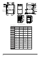
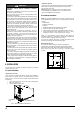
24-13/16”(630mm) 24-13/16”(630mm) 24-1/2”(622mm) 2-1/8”(54mm) 7-7/16”(189mm) 3-1/8”(79mm) D 19-1/2”(495mm) DIA.LEFT VENT OUTLET 4-3/4”(120.7mm) DIA.RIGHT HAND GAS ENTRY 1-1/2”(38mm) 11-3/16”(284mm) DIA.JUNCTION BOX LOCATION 7/8”(22mm) DIA.LEFT HAND GAS ENTRY 1-1/2”(38mm) DIA.JUNCTION BOX LOCATION 7/8”(22mm) 33-3/4”(857mm) 24-1/2”(622mm) DIA.THERMOSTAT DIA.
2. INTRODUCTION This series 4-way multipoise Category I fan-assisted furnace is CSA design-certified. A Category I fan-assisted furnace is an appliance equipped with an integral mechanical means to either draw or force products of combustion through the combustion chamber and/or heat exchanger. The furnace is factory-shipped for use with natural gas. This furnace is not approved for installation in mobile homes, recreational vehicles, or outdoors.
3.5 Acoustical Lining and Fibrous Glass Duct 3. CODES AND STANDARDS Follow all national and local codes and standards in addition to these instructions. The installation must comply with regulations of the serving gas supplier, local building, heating, plumbing, and other codes. In absence of local codes, the installation must comply with the national codes listed below and all authorities having jurisdiction.
● Before removing a new control from its container, discharge your body's electrostatic charge to ground to protect the control from damage. If the control is to be installed in a furnace, follow items 1 through 4 before bringing the control or yourself in contact with the furnace. Put all used and new controls into containers before touching ungrounded objects. ● An ESD service kit (available from commercial sources) may also be used to prevent ESD damage.
Side Return Air Inlet CAUTION PERSONAL INJURY AND/OR HAZARD PROPERTY DAMAGE Improper use or installation of this furnace may cause premature furnace component failure. This gas furnace may be used for heating buildings under construction provided that: - The furnace is permanently installed with all electrical wiring, piping, venting and ducting installed according to these installation instructions.
TABLE 2 - OPENING DIMENSIONS - IN.
LINE CONTACT ONLY PERMISSIBLE BETWEEN LINES FORMED BY INTERSECTIONS OF THE TOP AND TWO SIDES OF THE FURNACE JACKET AND BUILDING JOISTS , STUDS , OR FRAMING. VENT(Maintain required clearances to combustibles) Return Air Supply Air SEDIMENT TRAP Sheet metal in front of furnace combustion air Openings is Recommended Fig. 11 - Typical Attic Installation 6.
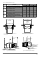
Vent the furnace with the appropriate connector as shown in Fig. 12-18. Fig. 12 - Downflow Application- Vent Elbow Up then Left Fig. 14 -Horizontal Left Application-Vent Elbow Up Fig. 16 -Upflow Application-Vent Elbow Left Fig. 13- Downflow Application- Vent Elbow Up then Right Fig. 15 -Horizontal Right Application-Vent Elbow Up Fig. 17 -Upflow Application-Vent Elbow Up Fig.
6.4 Filter Arrangement 6.5 Air Ducts General Requirements WARNING CARBON MONOXIDE AND POISONING HAZARD Failure to follow this warning could result in personal injury, or death. Never operate a furnace without a filter or with filter access door removed. FILTER SIZE See recommended filter size and type in Table 4. One of the most common causes of a problem in furnace is a blocked or dirty filter. The filter must be inspected monthy for dirt accumulation and replace it if neccessarily.
Table 3 - Air Delivery - CFM (Without Filter) FURNACE RETURN-AIR SIZE INLET * # ** EXTERNAL STATIC PRESSURE (IN.WC) SPEED 0.1 0.2 0.3 0.4 0.5 0.6 0.7 0.8 0.9 1.
7 VENT SYSTEM 7.3 Venting Into An Existing Chimney 7.1 Vent Connections This furnace may not be connected to any masonry chimney. However, an existing masonry chimney may be used on as a chase through which the metal vent pipe passes. Fig. 20 , “Combustion Air Inducer” shows the furnace as it is shipped from the factory. To convert to a horizontal or downflow position, remove the four screws that secure the inducer assembly and rotate 90 being careful not to damage the gasket. Reinstall screws.
a. WARNING When a Category I furnace is removed or replaced, the original venting system may no longer be correctly sized to properly vent the attached appliances. An improperly sized vent system can cause CARBON MONOXIDE to spill into the living space causing personal injury, and or death. 1 square in per 3000 Btu per hour (734 mm2/kW) of the total input rating of all equipment located in the enclosure. b. 3. 4.
Horizontal portions of the venting system shall be supported to prevent sagging using hangers or perforated straps and must slope upwards not less than 1/4” per foot (0.635 cm/m) from the furnace to the vent terminal. It is recommended that you follow the venting safety procedure below. This procedure is designed to detect an inadequate ventilation system that can cause the appliances in the area to operate improperly causing unsafe levels of Carbon Monoxide or an unsafe condition to occur.
8.2 High Altitude Derate NOTE: Adjusting the minimum supply pressure below the limits in the above table could lead to unreliable ignition. Gas input to the burners must not exceed the rated input shown on the rating plate. Overfiring of the furnace can result in premature heat exchanger failure. Gas pressures in excess of 13 inches water column can also cause permanent damage to the gas valve. Alternately standard derate for altitude from National Fuel Gas Code ANSI Z223.1 of 4% per 1000' may be taken.
8.3 Propane Gas Conversion To Convert From Natural to LP Gas on Gas Valve Possible property damage, personal injury or death may occur if the correct conversion kits are not installed. the appropriate kits must be applied to insure safe and proper furnace operation. all conversions must be performed by a qualified installer or service agency. This unit is configured for natural gas. The appropriate manufacturer's propane gas conversion kit (PRT. NO.
The following stipulations apply when connecting gas piping. Use black iron or steel pipe and fittings for the building piping. Use pipe joint compound on male threads only. Pipe joint compound must be resistant to the action of the fuel used. Use ground joint unions. Install a drip leg to trap dirt and moisture before it can enter the gas valve. The drip leg must be a minimum of three inches long.
9 ELECTRICAL CONNECTIONS WARNING ELECTRICAL SHOCK HAZARD Failure to follow this warning could result in personal injury or death. Blower access panel door switch opens 115V power to control. No component operation can occur. Do not bypass or close switch with panel removed. See Fig. 27 for field wiring diagram showing typical field 115V wiring. Check all factory and field electrical connections for tightness. Field-supplied wiring shall conform with the limitations of 63°F (35°C) rise.
9.4 Bx Cable Installation In Furnace J-box 2. Remove the desired electrical box hole knockout and position the hole in the electrical box over the hole in the furnace casing. 3. Fasten the electrical box to casing by driving two field-supplied screws from inside electrical box into casing steel. 4. Remove and save two screws holding J-Box. (See Fig. 25.) 5. Pull furnace power wires out of l/2-in. (13 mm) diameter hole in J-Box. Do not loosen wires from strain-relief wire-tie on outside of J-Box. 6.
D IP SW I T C H H E A T " O F F " DE L A Y SW3 ON SW 4 ON SECS. OFF ON ON OFF 90 120 OFF OFF 180 60 * * F A CT O R Y S E T Option Switch Positions Neutral terminal Fuse IND IGN IND N IGN N Thermostat Humidifier Input voltage 115V,60Hz Unused circulator blower terminal EAC Unused circulator blower terminal Heat stage Cool stage 1234 Option Switch LED OPERATION & DIAGNOSTIC LIGHT Fig.
10. START-UP, ADJUSTMENT, AND SAFETY CHECK 10.1 General WARNING 3. This furnace is also equipped with a self-diagnosing electronic control module. In the event a furnace component is not operating properly, the control module LED will flash on and off in a factoryprogrammed sequence, depending on the problem encountered. This light can be viewed through the observation window in the blower access door. Refer to the Troubleshooting Chart for further explanation of the lighting codes.
10.4 Sequence of Operation NOTE: Furnace control must be grounded for proper operation or control will lock out. Control is grounded through green wire routed to gas valve and manifold bracket screw. follow the sequence of operation through the different modes. Read and follow the wiring diagram very carefully.
10.5 Gas Manifold Pressure Measurement And Adjustment Measure gas manifold pressure with burners firing. Adjust manifold pressure per the Manifold Gas Pressure table. Table 13 - Manifold Gas Pressure CAUTION Manifold Gas Pressure To prevent unreliable operation or equipment damage, the gas manifold pressure must be as specified on the unit rating palte. Only minor adjustments should be made by adjusting the gas valve pressure regulator.
HEAT EXCHANGER RADIATIO “LINE OF SIGHT” Supply Air 4. Connect all unused blower motor leads to the "PARK" terminals on the integrated control module. Any leads not connected to the "PARK" terminals must be taped. 5. Turn ON power to furnace. 6. Verify proper temperature rise as outlined in Temperature Rise section. CIRCULATOR BLOWER FAN TIMING ADJUSTMENT NOTE: Items in this section refer to the air circulator blower fan, NOT to the induced draft blower.
12 SAFETY CIRCUIT DESCRIPTION 13 TROUBLESHOOTING 12.1 General 13.1 Electrostatic Discharge (Eso) Precautions A number of safety circuits are employed to ensure safe and proper furnace operation. These circuits serve to control any potential safety hazards and serve as inputs in the monitoring and diagnosis of abnormal function. These circuits are continuously monitored during furnace operation by the integrated control module. NOTE: Discharge body's static electricity before touching unit.
Table 14 - Troubleshooting Chart TROUBLE SHOOTING CHART Symptoms of Abnormal Operation •Furnace fails to operate. •Integrated control module diagnosic LED provides NO SIGNAL • Furnace fails to operate • Integrated control module diagnostic LED is flashing ONE (1) flash. • Furnace fails to operate.
TROUBLE SHOOTING CHART Symptoms of Associated Fault Description(s) Abonormal Operation LED • Furnace fails to • Rollout limit open. operate. • Integrated control module diagnostic 5 LED is flashing FLASHES FIVE (5) flashes. Possible reason • Flame rollout. • Misaligned burners, blocked flue or failed induced draft blower. • Loose or improperly connected wiring. Faulty rollout limit. •Induced draft blower • Polarity of 115 Volt AC • Polarity of 115 power to furnace or runs continuously.
14 SERVICE AND MAINTENANCE PROCEDURES WARNING ELECTRICAL SHOCK, FIRE OR EXPLOSION HAZARD Failure to follow safety warnings exactly could result in dangerous operation, serious injury, death or property damage. Improper servicing could result in dangerous operation, serious injury, death or property damage. • • • Before servicing, disconnect all electrical power to furnace. When servicing controls, label all wires prior to disconnecting. Reconnect wires correctly. Verify proper operation after servicing.
14.6 Cleaning Heat Exchanger The following steps should be performed by a qualified service agency: NOTE: If the heat exchangers get a heavy accumulation of soot and carbon, they should be replaced rather than trying to clean them thoroughly.
15. Reinstall vent connector on furnace vent elbow. Securely fasten vent connector to vent elbow with 2 field-supplied, corrosion-resistant, sheet metal screws located 1800 apart. 16. Replace blower access door only, if it was removed. 17. Set thermostat above room temperature and check furnace for proper operation. 18. Verify blower airflow and speed changes between heating and cooling. 19. Check for gas leaks. 20. Replace outer access door.
15 WIRING DIAGRAMS Models: 70A3A, 80B4A 80C4A, 90B4A, 100C5A, 100D5A, 110C5A, 120D5A, 135D5A I&O manual 33
Models: 50A3A 3 4 I&O manual 34