
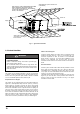
Installation Guide

14
I&O manual
WARNING
This type of installation requires that the supply air to the applian-
ce(s) be of a sufficient amount to support all of the appliance(s) in
the area. Operation of a mechanical exhaust, such as an exhaust
fan, kitchen ventilation system, clothes dryer or fireplace may cre-
ate conditions requiring special attention to avoid unsatisfactory
operation of gas appliances. A venting problem or a lack of supp-
ly air will result in a hazardous condition, which can cause the ap-
pliance to soot and generate dangerous levels of CARBON MINO-
XIDE, which can lead to serious injury, property damage and I or
death.
An
unconfined space
is not less than 50 cu.ft (1.42m
3
) per 1,000Btu/hr
(0.2928 kW) input rating for all of the appliances installed in that area.
Rooms communicating directly with the space containing the appliances
through openings not furnished with doors, are considered a part of the
unconfined space.
In unconfined spaces (see definition below) in buildings, infiltration may
be adequate to provide air for combustion ventilation and dilution of flue
gases. However, in buildings of tight construction (for example, weather
stripping, heavily insulated, caulked, vapor barrier, etc.), additional air
may need to be provided using the methods described in “An confined
space” section.
An
confined space
is an area with less than 50 cu . ft (1.42m
3
) per 1,000
Btu/hr (0.2928 kW) input rating for all of the appliances installed in that
area. The following must be considered to obtain proper air for
combustion and ventilation in confined spaces.
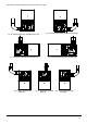
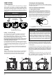
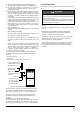
Fig. 20 , “Combustion Air Inducer” shows the furnace as it is shipped
from the factory. To convert to a horizontal or downflow position,
remove the four screws that secure the inducer assembly and rotate 90
being careful not to damage the gasket. Reinstall screws. Remove cap
from appropriate vent outlet location on the cabinet cut insulation in
cabinet to same size as the hole provided and reinstall cap in the hole in
the top panel.
Fig . 20
Combustion Air Inducer
Mounting Screw (Remove)
Flue Transition
(Do Not Remove)
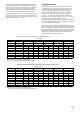
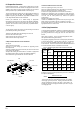
Fig. 22 Outside and Ambient Combustion Air
Gable
Vent
Gas
Vent
Soffit
Vent
Ventilated
Attic
Top Above
Insulation
Optional
Inlet (a)
Outlet
Air (a)
Ventilated
Crawl Space
Gas
Water
Heater
Soffit
Vent
Gas
Water
Heater
Inlet
Air (a)
Inlet
Air (b)
Gas
Vent
Outlet
Air (a)
Outlet
Air (b)
Inlet
Air (a)
Inlet
Air (b)
Gas
Water
Heater
Ventilated
Attic
Top Above
Insulation
Gable
Vent
Gas
Vent
In downflow applications, do not block the combustion air inlet.
The furnace must be installed on a coil cabinet or subbase to
allow combustionair to enter the burner compartment.
IMPORTANT
7 VENT SYSTEM
7.1 Vent Connections
CATEGORY 1 - 450 F. MAX. VENT TEMP.
7.2 Venting
7.3 Venting Into An Existing Chimney
The furnace shall be connected to a type B vent connector, The furnace shall not
be connected to a chimney flue serving a separate appliance designed to burn
solid fuel. Single-wall vent pipe is not allowed.
The venting system must be installed in accordance with Section 5.3
Air for combustion and Ventilation, of the National Fuel Gas Code
Z223.1/NFPA 54 (latest edition), or Sections 7.2, 7.3 or 7.4 of CSA
B149.1, National Gas and Propane Codes (latest edition) or applicable
provisions of the local building code and these instructions.
It is recommended that the appliance is installed in a location where the
space temperature is 32 °F( 0 °C) or higher. If the appliance is installed
in a location where the temperature is below 32 °F (0 °C) , the combustion
byproducts could condense causing damage to the appliance heat
exchanger.
This appliance may be common vented with another gas appliance for
residential installations as allowed by the codes and standards listed in
these instructions.
Category I venting consists of vertically venting one or more appliances
in B-vent or B-vent connectors. Type B-vent system extends in a gen-
eral vertical direction and does not contain offsets exceeding 45° .
A vent system having not more than one 60° offset is permitted.
This furnace may not be connected to any masonry chimney. However,
an existing masonry chimney may be used on as a chase through which
the metal vent pipe passes.
Fig. 21: Combustion Airflow Path Through The Furnace Casing to
the Burner Box
Combustion Air
90
90
7.4.1 Ambient Combustion Air Supply
7.4 Air For Combustion and Ventilation
This type installation will draw the air required for combustion from
within the space surrounding the appliance and from areas or rooms
adjacent to the space surrounding the appliance. This may be from
within the space in a non-confined location or it may be brought into
the furnace area rom outdoors through permanent openings or ducts.
A single, roperly sized pipe from the furnace vent connector to the
outdoors must be provided. For upflow models combustion air is
brought into the furnace through the unit top panel opening.