THIS BOOKLET CONTAINS IMPORTANT INFORMATION INSTALLER: USE THE INFORMATION IN THIS BOOKLET TO INSTALL THE APPLIANCE AND AFFIX THIS BOOKLET ADJACENT TO THE APPLIANCE AFTER INSTALLATION. USER: KEEP THIS BOOKLET OF INFORMATION FOR FUTURE REFERENCE. SERVICER: USE THE INFORMATION IN THIS BOOKLET TO SERVICE THE APPLIANCE AND AFFIX THE BOOKLET ADJACENT TO THE APPLI ANCE AFTER SERVICING. “NOTE: Please read all instruction in the manual and retain all manuals for futrue reference.
Installation,Start-up,Operating and Service and Maintenance Instructions CONTENTS PAGE 1.SAFETY CONSIDERATIONS....................................................................2 10.7 Temperature Rise Adjustment.................................................33 2. INTRODUCTION....................................................................................5 10.8 Circulator Blower Speed Adjustment.......................................34 3.CODES AND STANDARDS.......................................
1. SAFETY CONSIDERATIONS WARNING FIRE, EXPLOSION, ELECTRICAL SHOCK, AND CARBON MONOXIDE POISONING HAZARD ● Use only with type of gas approved for this furnace. Refer to the furnace rating plate. Failure to follow this warning could result in dangerous operation, serious injury, death,or property damage.
● Following instruction of lighting/ shutdown operation. Should the gas supply fail to shut off or if overheating occurs, shut off the gas valve to the furnace before shutting of the electrical supply. ● Before heating season begins, exame the furnace to determine that: a. All flue gas carrying areas external to the furnace (i.e. chimney, vent connector) are clear and free of obstructions. b. The vent connector is in place, slopes upward and is physically sound without holes or exccessive corrosion. c.
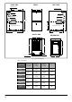
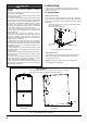
RIGHT SIDE LEFT SIDE FRONT Combustion Air Inlet Combustion Air Inlet A 19-1/2”(495mm) Gas Pipe Entry Gas Pipe Entry Vent Outlet Electrical Entry Electrical Entry Condensate Drain Condensate Drain 33-3/4”(857mm) Thermostat Wiring Thermostat Wiring 14”(355mm) RIGHT SIDE RETURN AIR LEFT SIDE RETURN AIR 28-3/4”(730mm) 22-13/16”(580mm) SUPPLY END RETURN END D 26-1/2”(672mm) 25-3/4”(655mm) 24”(610mm) Vent Outlet Combustion Air Inlet E Fig.
2. INTRODUCTION This series 3-way multipoise Category IV fan-assisted furnace is ETL design-certified. A Category IV fan-assisted furnace is an appliance equipped with an integral mechanical means to either draw or force products of combustion through the combustion chamber and/or heat exchanger. The furnace is factory-shipped for use with natural gas. This furnace is not approved for installation in mobile homes, recreational vehicles, or outdoors.
3.5 Acoustical Lining and Fibrous Glass Duct 3. CODES AND STANDARDS Follow all national and local codes and standards in addition to these instructions. The installation must comply with regulations of the serving gas supplier, local building, heating, plumbing, and other codes. In absence of local codes, the installation must comply with the national codes listed below and all authorities having jurisdiction.
● Before removing a new control from its container, discharge your body's electrostatic charge to ground to protect the control from damage. If the control is to be installed in a furnace, follow items 1 through 4 before bringing the control or yourself in contact with the furnace. Put all used and new controls into containers before touching ungrounded objects.
6. INSTALLATION CAUTION PERSONAL INJURY AND/OR HAZARD PROPERTY DAMAGE Improper use or installation of this furnace may cause premature furnace component failure. This gas furnace may be used for heating buildings under construction provided that: - The furnace is permanently installed with all electrical wiring, piping, venting and ducting installed according to these installation instructions.
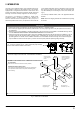
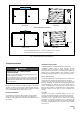
Horizontal Left Side Installation 1/2”~3/4” FRONT VIEW SIDE VIEW Horizontal Right Side Installation 1/2”~3/4” FRONT VIEW SIDE VIEW Tilt the unit slightly (minimum 1/2"(12.7mm) to maximum of 3/4"(19mm)) from back to front to aid in the draining of the heat exchanger. Fig. 7 - Horizontal Application-Setting Equipment 6.2 Horizontal Installation WARNING FIRE, EXPLOSION, AND CARBON MONOXIDE POISONING HAZARD Failure to follow this warning could result in personal injury, death, and/or property damage.
ALTERNATE ELECTRICAL AND GAS LINE CONNECTIONS FURNACE SUSPENSION This furnace has provisions allowing for electrical and gas line connections through either side panel. In horizontal applications the connections can be made either through the “top” or “bottom” of the furnace. If the furnace is installed in a crawl space it must be suspended from the floor joist or supported by a concrete pad. Never install the furnace on the ground or allow it to be exposed to water.
6.3 Condensate Line And Over Flow Pressure Swtich CAUTION: FOR HORIZONTAL LEFT INSTALLATION (AIR DISCHARGE TO THE LEFT), HOSES OF CONDENSATE OVERFLOW PRESSURE SWITCH NEED TO BE REROUTE. (SEE FIGURE XX) To achieve higher energy efficiency than non-condensing furnace, condensing furnace will generate significant amount of condensate water from combustion to recover latent heat in flue. Condensate generated from flue must be collected and discharged to drain line.
6.3.2 For Upflow Installation 1. Top venting (see Fig. 11) Connect vent pipe and air intake pipe (if applicable) to the couplers on the furnace top panel. Use street 2 to 3” transition for 3” pipe. Depend on which side the condensate trap to be mounted, remove 2 knockouts on the side where trap be mounted. Mount trap with two screws provided. Cut and remove 1/4 inch from the end of the drain port on the rubber elbow.
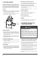
6.3.3 For Horizontal Installations 1. Air discharge to the right and vent through furnace top panel (see Fig. 13) Connect vent pipe and air intake pipe (if applicable) to the couplers on the furnace top panel. Use street 2 to 3” transition for 3” pipe. Use two field supplied elbows and nipples to make flue and air intake pipes vertical. Elbows should be as close to the furnace as possible.
AIR INLET High/Low Fire Pressure Switch HOSE CLAMP VENT OUTLET 14mm HOSE 14/16mm Tube 16mm HOSE HOSE CLAMP DRAIN TRAP DRAIN TRAP FIXING Fig. 14 - Horizontal Left Side Installation, Vent Through Top Panel AIR INLET VENT OUTLET High/Low Fire Pressure Switch 14mm HOSE HOSE CLAMP 14/16mm Tube 16mm HOSE DRAIN TRAP HOSE CLAMP DRAIN TRAP FIXING Fig.
6.4 Filter Arrangement WARNING CARBON MONOXIDE AND POISONING HAZARD Failure to follow this warning could result in personal injury, or death. Never operate a furnace without a filter or with filter access door removed. Filter Installation All applications require the use of a field installed filter.
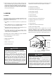
Table 2 - Air Delivery - CFM (Without Filter) * @ & # FURNACE SIZE 60B RETURN-AIR INLET Bottom or Sides 80B Bottom or Sides 80C Bottom or Sides 100C 100D 120D Bottom or Sides Bottom or Sides Bottom or Sides EXTERNAL STATIC PRESSURE (IN.WC) SPEED 0.1 0.2 0.3 0.4 0.5 0.6 0.7 0.8 0.9 1.
7. COMBUSTION AIR AND VENT SYSTEM 2. 7.1 Combustion Air And Vent Safety This Category IV, dual certified direct vent furnace is designed for residential application. It may be installed without modification to the condensate system in a basement, garage, equipment room, alcove, attic or any other indoor location where all required clearance to combustibles and other restrictions are met. The combustion air and the venting system must be installed in accordance with Section 5.
A IMPORTANT A A A Furnace vent pipe connections are sized for 2” (5.1 cm). pipe. Any pipe size change must be made outside the furnace casing in a vertical pipe section to allow proper drainage of condensate. An offset using two 45º (degree) elbows will be required for plenum clearance when the vent is increased to 3” (7.6 cm). STANDARD ELBOW Fig 18: LONG (SWEEP) ELBOW The final assembly procedure for the combustion air and vent piping is as follows: 1.
VENT CLEARANCES G A FIXED CLOSED D E L B B B V VENT TERMINAL X AIR SUPPLY H B I AREA WHERE TERMINAL IS NOT PERMITTED M C K B F B J FIXED CLOSED OPERABLE Fig 19: Home Layout Direct Vent Terminal Clearances Canadian Installations1,3 A. Clearance above grade, veranda, porch, deck, or 12” (30.5 cm) balcony US Installation2,3 12” (30.5 cm) B. Clearance to window or door that may be opened 12” (30.5 cm) for models 100,000 BTUH (30 kW), 36” (91 cm) for models >100,000 BTUH (30 kW).
7.5 Vent System This furnace is certified to be installed with one of two possible vent configurations. 12” MIN. 1. Horizontal vent system. This vent system can be installed completely horizontal or combinations of horizontal, vertical, or offset using elbows. 12” Minimum below overhang 12” MIN. 12” Minimum separation between bottom of combustion air intake and bottom of vent 2. Vertical vent system.
7.6 Combustion & Ventilation Air Requirements Combustion Air Supply All installations must comply with Section 5.3, Air for Combustion and Ventilation of the National Fuel Gas Code, ANSI Z223.1 or Sections 7.2, 7.3 or 7.4 of CAN/CGA B149.1 or .2 Installation Code - latest editions. The combustion air intake pipe should be located either through the wall (horizontal or side vent) or through the roof (vertical vent).
In unconfined spaces (see definition below) in buildings, infiltration may be adequate to provide air for combustion ventilation and dilution of flue gases. However, in buildings of tight construction (for example, weather stripping, heavily insulated, caulked, vapor barrier, etc.), additional air may need to be provided using the methods described in “An confined space” section. An confined space is an area with less than 50 cu . ft (1.42m 3) per 1,000 Btu/hr (0.
Horizontal portions of the venting system shall be supported to prevent sagging using hangers or perforated straps and must slope upwards not less than 1/4” per foot (0.635 cm/m) from the furnace to the vent terminal. It is recommended that you follow the venting safety procedure below. This procedure is designed to detect an inadequate ventilation system that can cause the appliances in the area to operate improperly causing unsafe levels of Carbon Monoxide or an unsafe condition to occur.
8 GAS SUPPLY AND PIPING WARNING FIRE OR EXPLOSION HAZARD Failure to follow this warning could result in personal injury, death, and/or property damage. Never purge a gas line into a combustion chamber. Never test for gas leaks with an open flame. Use a commercially available soap solution made specifically for the detection of leaks to check all connections. WARNING FIRE OR EXPLOSION HAZARD Failure to follow this warning could result in personal injury, death, and/or property damage.
8.2 High Altitude Derate When an appliance is installed at elevations above 4500ft (1350m), the certified high-altitude input rating shall be reduces at the rate of 4% for each additional 1000ft (300m). Alternately standard derate for altitude from National Fuel Gas Code ANSI Z223.1 of 4% per 1000' may be taken. Refer to the most recent version of ASNI Z223.1 for correct gas orifice. The orifices must be selected using the table below. The furnace derate is 4% for each 1,000 feet above sea level.
8.3 Propane Gas Conversion To Convert From Natural to LP Gas on Gas Valve Possible property damage, personal injury or death may occur if the correct conversion kits are not installed. the appropriate kits must be applied to insure safe and proper furnace operation. all conversions must be performed by a qualified installer or service agency. This unit is configured for natural gas. The appropriate manufacturer's propane gas conversion kit , must be applied for propane gas installations.
The following stipulations apply when connecting gas piping. Use black iron or steel pipe and fittings for the building piping. Use pipe joint compound on male threads only. Pipe joint compound must be resistant to the action of the fuel used. Use ground joint unions. Install a drip leg to trap dirt and moisture before it can enter the gas valve. The drip leg must be a minimum of three inches long.
9 ELECTRICAL CONNECTIONS WARNING ELECTRICAL SHOCK HAZARD Failure to follow this warning could result in personal injury or death. Blower access panel door switch opens 115V power to control. No component operation can occur. Do not bypass or close switch with panel removed. See Fig. 33 for field wiring diagram showing typical field 115V wiring. Check all factory and field electrical connections for tightness. Field-supplied wiring shall conform with the limitations of 63°F (35°C) rise.
9.4 Bx Cable Installation In Furnace J-box 2. Remove the desired electrical box hole knockout and position the hole in the electrical box over the hole in the furnace casing. 3. Fasten the electrical box to casing by driving two field-supplied screws from inside electrical box into casing steel. 4. Remove and save two screws holding J-Box. (See Fig. 31.) 5. Pull furnace power wires out of l/2-in. (13 mm) diameter hole in J-Box. Do not loosen wires from strain-relief wire-tie on outside of J-Box. 6.
Fig. 32 - Furnace Control FIELD 24V WIRING FIELD 115V, 208/230V, WIRING FACTORY 24V WIRING FACTORY 115V WIRING single stage cooling system thermostat TERMINALS NOTE 5 W2 W1 R C G Y NOTE 2 FOUR-WIRE HEATING-ONLY BLOWER DOOR SWITCH BLK 208/230V THREE PHASE W2 BLK WHT WHT GND 115V FIELDSUPPLIED DISCONNECT FIELD-SUPPLIED DISCONNECT GND J-BOX 24V TERMINAL BLOCK C O N T R O L W1 208/230V SINGLE PHASE R G C NOTE 1 Y YLO NOTE 4 NOTE 3 FURNACE GND CONDENSING UNIT TWO WIRE NOTES: 1.
10. START-UP, ADJUSTMENT, AND SAFETY CHECK 10.1 General WARNING 3. This furnace is also equipped with a self-diagnosing electronic control module. In the event a furnace component is not operating properly, the control module LED will flash on and off in a factoryprogrammed sequence, depending on the problem encountered. This light can be viewed through the observation window in the blower access door. Refer to the Troubleshooting Chart for further explanation of the lighting codes.
10.4 Sequence of Operation NOTE: Furnace control must be grounded for proper operation or control will lock out. Control is grounded through green wire routed to gas valve and manifold bracket screw. follow the sequence of operation through the different modes. Read and follow the wiring diagram very carefully.
10.5 Gas Manifold Pressure Measurement And Adjustment Measure gas manifold pressure with burners firing. Adjust manifold pressure per the Manifold Gas Pressure table. Table 15- Manifold Gas Pressure CAUTION Manifold Gas Pressure To prevent unreliable operation or equipment damage, the gas manifold pressure must be as specified on the unit rating palte. Only minor adjustments should be made by adjusting the gas valve pressure regulator.
HEAT EXCHANGER RADIATIO “LINE OF SIGHT” Supply Air 4. Connect all unused blower motor leads to the "PARK" terminals on the integrated control module. Any leads not connected to the "PARK" terminals must be taped. 5. Turn ON power to furnace. 6. Verify proper temperature rise as outlined in Temperature Rise section. CIRCULATOR BLOWER FAN TIMING ADJUSTMENT NOTE: Items in this section refer to the air circulator blower fan, NOT to the induced draft blower.
12 SAFETY CIRCUIT DESCRIPTION 13 TROUBLESHOOTING 12.1 General 13.1 Electrostatic Discharge (Eso) Precautions A number of safety circuits are employed to ensure safe and proper furnace operation. These circuits serve to control any potential safety hazards and serve as inputs in the monitoring and diagnosis of abnormal function. These circuits are continuously monitored during furnace operation by the integrated control module. 12.
Table 16- Troubleshooting Chart Green LED Flash Amber LED Flash Red LED Flash Error/Condition Comments/Troubleshooting 1 Flame sensed when no flame should be present Verify the gas valve is operating and shutting down properly. Flame in burner assemble should extinguish promptly at the end of the cycle. Check orifices and gas pressure. 2 Pressure switch stuck closed/ inducer error Pressure switch stuck closed. Check switch function, verify inducer is turning off.
14 SERVICE AND MAINTENANCE PROCEDURES WARNING ELECTRICAL SHOCK, FIRE OR EXPLOSION HAZARD Failure to follow safety warnings exactly could result in dangerous operation, serious injury, death or property damage. Improper servicing could result in dangerous operation, serious injury, death or property damage. • • • Before servicing, disconnect all electrical power to furnace. When servicing controls, label all wires prior to disconnecting. Reconnect wires correctly. Verify proper operation after servicing.
14.8 Repair And Replacement Parts 14.6 CONDENSATE TRAP AND DRAIN SYSTEM (QUALIFIED SERVICER ONLY) Annually inspect the drain tubes, drain trap, and field-supplied drain line for proper condensate drainage. Check drain system for hose connection tightness, blockage, and leaks. Clean or repair as necessary. 14.7 Before Leaving An Installation • When ordering any of the listed functional parts, be sure to provide the furnace model, manufacturing, and serial numbers with the order.
15 WIRING DIAGRAMS (9) 10 GR W2 OG RD PU W1 BL BR YLO BR PU RD GR E1 7 3 4 3 5 E1 9 L1 XFMR E2 0 BR AT HE HI G/Y BL OG BR BR L1 WH BK PU PU PU PU RD WH PU 1 Flash = Flame sensed when no flame should be present 2 Flash = Pressure switch stuck closed/ inducer error 3 Flash = 1st-stage pressure switch stuck open/inducer error 4 Flash = Open limit switch 5 Flash = Open rollout/open fuse detect 6 Flash = 1st-stage pressure switch cycle lockout 7 Flash = External lockout (retries) 8