
Installation Guide
30
I&O manual
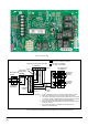
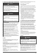
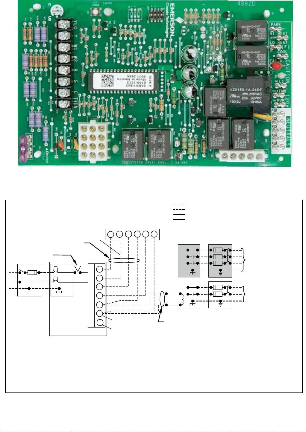
Fig. 32 - Furnace Control
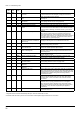
Fig.33 - Heating and Cooling Application Wiring Diagram with 2-Stage heatingThermostat
115V FIELD-
SUPPLIED
DISCONNECT
J-BOX
24V
TERMINAL
BLOCK
FOUR-WIRE
HEATING-ONLY
NOTE 1
NOTE 2
FIELD-SUPPLIED
DISCONNECT
CONDENSING
UNIT
TWO
WIRE
FURNACE
C
O
N
T
R
O
L
R
G
C
GND
GND
FIELD 24V WIRING
FIELD 115V, 208/230V, WIRING
FACTORY 24V WIRING
FACTORY 115V WIRING
208/230V
THREE
PHASE
208/230V
SINGLE
PHASE
BLOWER DOOR
SWITCH
WHT
BLK
WHT
BLK
NOTES: Connect Y-terminal in furnace as shown for proper blower operation.
Some thermostats require a "C" terminal connection as shown.
If any of the original wire, as supplied, must be replaced, use
same type or equivalent wire.
GND
single stage cooling system thermostat
TERMINALS
1.
2.
3.
R
G
Y
C
Y
W1
W1
YLO
W2
W2
NOTE 3
YLO connect two-stage cooling thermostat Y1(first stage cool) terminal.
4.
Y connect two-stage cooling thermostat Y2(second stage cool) terminal.
Y connect single stage cooling system thermostat Yterminal.
NOTE 4
5.
NOTE 5
Please connect W1 with single stage heat system thermostat terminal
W,and w2 reserved.
6.