The Signature Series is NOT designed for amateur installation. Installation SHOULD be performed by an authorized technician. Please read this manual carefully before installation and keep it for future reference. Owner & Installation Manual Signature Series MAHM*ETA AIR Handler The Signature Series is NOT designed for amateur installation. Installation SHOULD be performed by an authorized technician. Please read this manual carefully before installation and keep it for future reference.
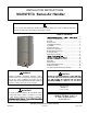
INSTALLATION INSTRUCTIONS MAHM*ETA Series Air Handler This manual must be left with the homeowner for future reference. This is a safety alert symbol and should never be ignored. When you see this symbol on labels or in manuals, be alert to the potential for personal injury or death. Table of Contents .......2 Shipping and Packing List ...........................................3 General........................................................................3 Requirements ................................
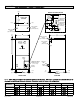
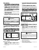
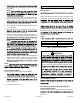
MAHM*ETA 1 (25) DETAIL OF PIPING PLATE SUPPLY AIR OPENING 14-1/2 (368) 1 (25) 4-3/8 (111) LOW VOLTAGE INLETS (Top and Right Side) LINE VOLTAGE INLETS (Top and Left Side) CONDENSATE DRAINS (2) (Upflow and Downflow) 2-3/4 (70) 3-1/2 (89) 1-3/4 (44) TOP VIEW 3/4 (19) CONDENSATE DRAINS (2) (Horizontal) 2-3/8 (60) C 1 (25) 4-3/4 (121) 3/4 (19) SUCTION LINE LIQUID LINE 22 (559) B LINE VOLTAGE INLETS (Top and Right Side) CIRCUIT BREAKER COVER LOW VOLTAGE INLETS (Either Side) AIR FLOW A PIPING
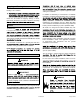
Shipping and Packing List pertaining to this type of equipment should be determined as the instructions supplied in separate equipment, before starting the installation. Package 1 of 1 contains: In addition to conforming to manufacturer’s installation instructions and local municipal building codes, installation Check the air handler for shipping damage; if found, immediately contact the last carrier. Check the unit rating General The MAHM*ETA is designed for indoor installation only.
IMPORTANT single-story buildings. Excessive condensation may occur if the unit is installed When a MAHM*ETA unconditioned space, apply sealant around electrical be: Apply sealant on the inside of the cabinet at the • 320 square inches for -024 models; • 360 square inches for -030 and -036 models; • 450 square inches for -042 thru -060 models electrical controls. determine if the open area meets the minimum open area listed above.
3. 1. end of the unit and level from front to back of unit (see Figure 7). The air handler must be supported on the bottom only 4. frame. 5. 2. horizontal drain pan. If the unit is suspended, the entire length of the cabinet must be supported. If you use a chain or strap, use a piece of angle iron or sheet metal attached to the unit NOTE: 3. Place the unit in the desired location and slope unit. Connect return and supply air plenums as required 4.
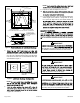
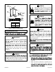
NOTE: TOP CAP ROTATED TO CORRECT POSITION 9. TOP CAP SCREWS CABINET SUPPORT Flip access door and replace it on the unit. 10. end of the unit. Connect return and supply air plenums 90º BEND DRAIN PAN REINSTALLED HERE 11. If suspending the unit, it must be supported along the entire length of the cabinet. If using chain or strap, use a piece of angle iron or sheet metal attached to DRAIN PAN SHIPPING LOCATION illustrated in Figure 3.
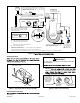
OVERFLOW DRAIN LINE ABOVE FINISHED SPACE? ALWAYS RUN AN OVERFLOW DRAIN LINE. IF NOT POSSIBLE TO ROUTE OVERFLOW DRAIN LINE, INSTALL LOW VOLTAGE OVERFLOW SWITCH KIT. WIRE KIT TO SHUT DOWN COMPRESSOR PER INSTRUCTIONS.
2. and connect primary drain line to the main drain pan connection. NOTE: Duct System and Filters Duct System of the supply plenum. 3. If the secondary drain line is to be used, remove the plug or the knockout and route the drain line so that Supply and return duct system must be adequately sized to meet the system’s air requirements and static pressure requirements on the secondary drain line. conditioned areas or 2” minimum in unconditioned areas. 4.
Cabinet and Duct Flange WARNING CABINET DOOR FLANGE When using a high pressure gas such as nitrogen to pressurize a refrigeration or air conditioning system, use a regulator that 1−1/2 (38) DUCT FLANGE 3/4 (19) DUCT ADAPTER 3/4 (19) 3/4 (19) WARNING 3/4 (19) ”A” 1−1/2(38) psig (6.9 to 13.8 kPa). BOTTOM OF CABINET charge from only the high side may result in BRAKEDOWN90 DEGREES 1/2 (13) 1/4 (6) DIA. 2−HOLES UNIT SIZE 1−1/2 (38) suction tubing.
PLEASE READ IMPORTANT ISSUES CONCERNING BRAZING OPERATIONS IN THE BRAZING REFRIGERANT LINES SECTION BEFORE PROCEEDING. NOTE - REFER TO OUTDOOR UNIT INSTALLATION INSTRUCTIONS FOR REFRIGERANT PIPING SIZE REQUIREMENTS. NOTE - Use silver alloy brazing rods with five or six percent minimum silver alloy for copper-to-copper brazing, 45 percent alloy for copper-to-brass and copper-to-steel brazing.
3. To avoid damaging the rubber grommets in the cabinet Electrical Connections source. WARNING NOTE: 4. 5. supplies before servicing. Connect the suction and liquid lines to the evaporator coil. Take care to protect the cabinet and internal components as detailed in Figure 10. Replace all parts and panels before operating. Failure to do so can result in death or electrical shock. Braze using an alloy of silver or copper and phosphorus NOTE: WARNING 6. NOTE: in one opening. 7.
• NOTE: current protection are to be supplied by the installer. Refer to the air handler rating plate for maximum over-current protection, minimum Select the proper supply circuit conductors in TOP through 4 in the Canadian Electric Code, Part I, CSA Standard C22.1. • • single phase, 60 cycles. For 208-volt applications, see “208 Volt Conversion” later in this section. • voltage and line voltage. Refer to the dimension • SIDE provided caps to seal holes not used.
Figure 14. Typical Wiring Diagram MAHM*ETA 507788-01C mrcool.
* * SEE NOTE * * * Figure 15. Page 14 of 20 mrcool.
Blower Performance Data Speed Tap 1 -24 -30 Application Fan Only -42 0.4 0.
Air Flow - Cooling Blower Speed Operation Inspection NOTE: capacity rating of the air handler (Tap 3). If the outdoor unit is smaller than the maximum cooling Pre-Start-Up Checks • Is the air handler properly and securely installed? • chart (Table 2). WARNING • Will the unit be accessible for servicing? • Has an auxiliary pan been provided under the unit ELECTRIC SHOCK HAZARD! could cause damage? servicing. • Replace all parts and panels before operating.
1. Set thermostat to call for auxiliary heat (approximately minimum of 3 minutes for all sequencers to cycle on. 2. Set the thermostat so that it does not call for heat. Operation W2 and E on the thermostat sub-base so that the electric heat control Maintenance When the thermostat calls for cooling, 24 volts is put on IMPORTANT relay energizes.
Cabinet Insulation Use of Air Handler During Construction It is not recommended to use this air handler unit during any IMPORTANT DAMAGED INSULATION MUST BE REPAIRED OR REPLACED before the unit is put back into operation. Air handler units may be used for heating (heat pumps) separated or torn. conditions are met: Matte- or foil-faced insulation is installed in indoor • conditions (surrounding ambient temperature and humidity) and the varying conditions inside the unit.
Installing Contractor’s Name_______________________ Installing Contractor’s Phone_______________________ Job Address____________________________________ Installing Date_______________________________ Air Handler Model #___________________________ Thermostat 9 SUPPLY AIR Disconnect Switch Line Voltage 3 8 2 Integrated Control Temperature 1 Duct System 6 Blower Motor Amps 7 Electric Heat Amps 5 Duct Static RETURN AIR 1 Filter DUCT SYSTEM 5 Sealed Insulated (if necessary) Registers Open and Unob
Installing Contractor’s Name_______________________ Installing Contractor’s Phone_______________________ Job Address____________________________________ 1 Duct System Thermostat 2 Integrated Filter Installing Date_______________________________ Air Handler Model #___________________________ Disconnect Switch 9 Control Line Voltage 3 1 Duct System RETURN AIR SUPPLY AIR 6 Electric Heat Amps 4 Drain Line 7 Blower motor Amps 5 8 Duct Static 1 Temperature DUCT SYSTEM 5 dry coil SUPPLY AIR
Signature Series MAHM*ETA Air Handler ELECTRICIAN and/or HVAC TECHNICIAN: LICENSE #: INSTALLATION DATE: INSTALLATION LOCATION: SERIAL NUMBER: The design and specifications of this product and/or manual are subject to change without prior notice. Consult with the sales agency or manufacturer for details.