The Signature Series is NOT designed for amateur installation. Installation SHOULD be performed by an authorized technician. Please read this manual carefully before installation and keep it for future reference. Owner & Installation Manual Signature Series MPG*S*M414A Residential Package The Signature Series is NOT designed for amateur installation. Installation SHOULD be performed by an authorized technician. Please read this manual carefully before installation and keep it for future reference.
INSTALLATION AND MAINTENANCE INSTRUCTIONS MPG*S*M414A SERIES UNITS RESIDENTIAL PACKAGED UNITS Gas/Electric 507295-02C 4/2019 Table of Contents THIS MANUAL MUST BE LEFT WITH THE HOMEOWNER FOR FUTURE REFERENCE WARNING If this unit is to be installed in a mobile or manufactured home application, the duct system must be sized to achieve static pressures within the manufacturer’s guidelines. All other installation guidelines must also be followed.
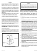
Installation Inspection These instructions must be saved for future reference. These units are single package air conditioners with gas heat designed for outdoor installation on a rooftop or a slab. The units are completely assembled. All piping, refrigerant charge, and electrical wiring are factory installed and tested. The units require only electric power, gas piping, condensate drain, and duct connections, plus installation of the vent cover at the point of installation.
Clearances All units require certain clearances for proper operation and service. Refer to Table 1 for the minimum clearances to combustibles, servicing, and proper unit operation. In made from wood or class A, B, or C roof covering material. Units must be installed outdoors. Do not permit overhanging structures or shrubs to obstruct condenser air discharge outlet, combustion air inlet, or vent outlet. Clearance to Combustibles Clearance for Service Access Front of unit 0 in. 24 in.
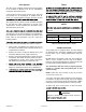
Venting The vent outlet must be installed in a location as to prevent building degradation and must be consistent with the National Fuel Gas Code, Z223.1 or CAN/CGA-B149.1 & .2. The products of combustion are discharged through a screened opening on the gas heat side panel. The horizontal vent system shall terminate at least 4 feet below, 4 feet horizontally from, or 1 foot above any door, window, or gravity air inlet into the building.
Duct System Filters The duct system should be designed and sized according to the methods in Manual Q of the Air Conditioning Contractors of America (ACCA). A closed return air duct system shall be used. This shall not preclude use of economizers or outdoor fresh air intake. It is recommended that supply and return air duct The supply and return air duct systems should be designed for the CFM and static requirements of the job.
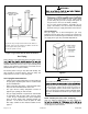
WARNING MINIMUM PITCH 1 IN (25) PER 10” (3048 MM) OF LINE causing injury or death may occur. UNIT • must be disconnected from the gas supply piping system during any pressure testing of that system at test pressures in excess of 1/2 PSIG (3.48kPa). OPEN VENT • A 1/8” N.P.T. plugged tapping, accessible for test gauge connections, must be installed immediately upstream of the gas supply connection to the furnace.
All LPG/propane gas equipment must conform to the safety standards of the National Fire Protection Association. For satisfactory operation, LPG/propane gas pressure must be a minimum of 11” w.c. at the unit under full load. of the type shown on the wiring diagram. Electrical wiring must be sized to carry minimum circuit ampacity marked on the unit. Use copper conductors only. Each unit must be wired with a separate branch circuit and be properly fused.
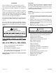
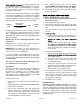
4. Turn on electrical power to the unit. 5. Set the room thermostat to the desired temperature. (If the thermostat “set” temperature is above room temperature after the pre-purge time expires, main burners will light.) Red To Shut Down Main Burners Blue Yellow 1. Turn off electrical power to unit. 2. Slide the gas valve switch to the “OFF” position (see Figure 7). White Regulator Adjustment Green Figure 7.
To adjust the regulator, turn the adjusting screw on the regulator clockwise to increase pressure and input or counterclockwise to decrease pressure and input. See Figure 7 to assist in locating the regulator on the gas valve. Check the furnace rate by observing the gas meter, making sure all other gas appliances are turned off. The test hand on the meter should be timed for at least one revolution, noting the number of seconds per revolution.
Operation Cooling System Performance Values Cooling System Model The cooling system is factory-charged with HFC-R-410A. The compressor is hermetically sealed and base-mounted with rubber-insulated bolts. Suction Superheat +/- 3° 2 Ton 13 2.5 Ton 16 Cooling Sequence of Operation When the thermostat calls for cooling, R is closed to Y (see the wiring diagrams). This action completes the low voltage control circuit, energizing the compressor, condenser fan motor, and blower motor. 3 Ton 14 3.
Maintenance Blower OFF Delay – Heating • The circulating air blower “OFF” delay is 120 seconds after shutting down the burners. This delay is not adjustable. • The circulating air blower “ON” delay is 120 seconds after “W” signal is received to allow the furnace to warm up. Periodic inspection and maintenance normally consists of coil. On occasion, other components of the furnace may also require cleaning.
Heat Exchanger Control System Diagnostics With proper combustion adjustment, the heat exchanger LED Status of a gas appliance is highly irregular and once cleaned, the cause of the sooting must be determined. If the heat exchanger should become sooted, it can be cleaned as follows: 1. Slow Flash Fast Flash Flashing Rate Normal operation: second No call for heat Normal operation: second Call for heat 2 Flash second with 1-second pause Failed to detect or 3 Flash 1.
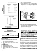
L1 CMB BLWR ACB ACB COOL HEAT BLK N B3 TRANSFORMER T1 RED GRN BLU 3 4 S4 S79 YEL BLK N G 1 L C KI Y G W1 R THERMOSTAT CONTROL CIRCUIT WIRING TO BE 24 VOLT, N.E.C. CLASS 2 HEAT ANTICIPATION SETTING: 0.
Signature Series MPG*S*M414A Residential Package ELECTRICIAN and/or HVAC TECHNICIAN: LICENSE #: INSTALLATION DATE: INSTALLATION LOCATION: SERIAL NUMBER: The design and specifications of this product and/or manual are subject to change without prior notice. Consult with the sales agency or manufacturer for details.