The Signature Series is NOT designed for amateur installation. Installation SHOULD be performed by an authorized technician. Please read this manual carefully before installation and keep it for future reference. Owner & Installation Manual Signature Series MPC*1M414A & MPH*1M414A Residential Packaged Units The Signature Series is NOT designed for amateur installation. Installation SHOULD be performed by an authorized technician.
INSTALLATION AND MAINTENANCE INSTRUCTIONS MPC*1M414A & MPH*1M414A Air Conditioners and Heat Pumps C Table of Contents THIS MANUAL MUST BE LEFT WITH THE HOMEOWNER FOR FUTURE REFERENCE WARNING Installation and servicing of air conditioning equipment can be hazardous due to internal refrigerant pressure and live electrical components. Only trained and Installation ...................................................................2 Electrical Wiring...........................................................
Location WARNING clearance for free entrance to the air inlet and discharge or maintenance can cause injury or property damage. Refer to this manual. For assistance or additional service access. agency. Installation not settle or shift. Adequate structural support must be provided. Install the unit in level position. Isolate the base from the building structure to avoid possible transmission of sound or vibration into the conditioned space.
P - PACKAGED de r pen ady GRN P-6 W1 C L R O Y1 W1 & W2 CAN BE USED TO STAGE ELECTRIC HEAT ACCESSORY ON 15 & 20KW MODELS Access to all serviceable components is provided by four 24 V G P-5 WHT BLU RED YEL ORN WHT 5, 7.5 & 10KW HEATER ACCESSORIES FUNCTION OFF W1 ONLY. FAN 2 DEFROST CONTROL O-OUT LO-PS 2 DF COMMON HI-PS Y1 OUT NOTE: IF ANY OF THE ORIGINAL WIRE IS REPLACED THE SAME SIZE AND TYPE WIRE MUST BE USED.
or pigtail leads located on the main control box and are * CAUTION * “O” connection used only on heat pump models during normal operation. Units are factory wired for a 230-volt power supply. If power supply is 208 volts, it will be necessary to change a wire connection on the unit transformer from 240V terminal to 208V terminal as shown on the wiring diagram. Use only copper conductors. Thermostat off W1 only. The room thermostat should be located on an inside Figure 4.
NOTE: Install drain lines and trap so they do not block service access to the unit. 1. the unit base insulation to access bottom metal covers underneath the insulation. 2. See Figure 5 for proper drain arrangement. The drain line must pitch to an open drain or pump to prevent clogging material to prevent air leakage into the return air system. 3. bottom duct connections or roof curb seals. CAUTION 4. 5. Minimum Pitch: Filters Open NOTE: Mounting Frame is limited.
Heating - Heat Pump Stage 2. and discard. 3. Remove the heater blockoff by removing the four 4. Insert the heater into the control panel and fasten in the same mounting holes. 5. and outdoor fan. The reversing valve is not energized in the heating mode. The thermostat again automatically stops unit operation. Heating - Auxiliary Electric Heat connections on the heater kit. Sequence of Operation continues to operate until all heating elements have turned off.
Defrost Control The defrost control board includes the combined functions The maximum defrost period is 14 minutes and cannot be adjusted. NOTE: heating operation to defrost mode and back. During the A test option is provided for troubleshooting. The test mode may be started any time the unit is in the heating mode and the defrost thermostat is closed or jumpered. If the jumper relay is energized and the defrost begins. 1.
The unit will remain locked out until power to the board is interrupted, then re-established, or until the jumper is applied to the TEST pins for 0.5 seconds. If the measured performance value varies from table value NOTE: The defrost control board ignores input from the low pressure switch terminals as follows: refrigerant to nameplate charge. It is critical that the exact • During the TEST mode system performance. • During the defrost cycle • • components.
Maintenance Motors Indoor and outdoor fan and vent motors are permanently lubricated and require no maintenance. WARNING Before performing maintenance operations on the constant torque motor. These motors remain energized and use Tap 3 for cooling speed and Tap 5 for heating speed. shock could cause personal injury or death. Outdoor Coil Periodic inspection and maintenance normally consists of the outdoor coil surface or other parts in the air circuit.
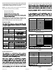
Table 9. Cooling Performance - HP Models 80 DB / 67 WB Deg.
Wiring Diagrams CRANK CASE HEATER (IF USED) HR1 BLK BLK G BLK CONNECTION DIAGRAM A/C (CONSTANT TORQUE BLOWER) SINGLE PHASE J2-1 B4 B3 J2-4 BLU RED BLU N 4 G 3 L 2 C 1 YEL B-3 WHT BLU S79 W1 & W2 CAN BE USED TO STAGE ELECTRIC HEAT ACCESSORY ON 10, 15 & 20KW MODELS J2-5 WHT 5 & 7.5KW HEATER ACCESSORIES FUNCTION OFF W1 ONLY. BLK J2-6 GRN S4 J1-11 Y R C W1 G S1 THERMOSTAT YEL CONTROL CIRCUIT WIRING TO BE 24 VOLT, N.E.C. CLASS 2 537663-01 WARNINGELECTRIC SHOCK HAZARD.
Figure 9.
Signature Series MPC*1M414A & MPH*1M414A Residential Package ELECTRICIAN and/or HVAC TECHNICIAN: LICENSE #: INSTALLATION DATE: INSTALLATION LOCATION: SERIAL NUMBER: The design and specifications of this product and/or manual are subject to change without prior notice. Consult with the sales agency or manufacturer for details.