Versa Pro Central Ducted 36-60K Installation & Owner’s Manual MODELS: CONDENSER: AIR HANDLER: MVP-36-HP-C-230-00 MVP-48-HP-C-230-00 MVP-60-HP-C-230-00 MVP-36-HP-MUAH-230-00 MVP-48-HP-MUAH-230-00 MVP-60-HP-MUAH-230-00 COMPLETE SYSTEM: MVP-36-HP-230-00 MVP-48-HP-230-00 MVP-60-HP-230-00 Read this manual carefully before installation and keep it where the operator can easily find it for future reference.
Contents CONTENTS 1 2 3 4 5 6 7 8 9 10 11 12 1 SAFETY...............................................................................................................................................3 ACCESSORIES....................................................................................................................................6 INDOOR UNIT INSTALLATION.........................................................................................................7 3.1 Indoor Unit Parts...........
Contents IMPORTANT INSTALLATION INFORMATION! Refrigerant Line Set Connection Options, Requirements, and Stipulations 18K/24K/30K Capacity Units - Are designed to use the MRCOOL® Quick Connect® Pre-Charged Line Set as the preferred type of refrigerant piping. If this method is used, you DO NOT have to retain the services of professional HVAC installer for this step. However, these capacity units can also be installed using a traditional flare nut configuration of refrigerant piping.
1 SAFETY Safety Precautions Read Before Using Incorrect usage may cause serious damage or injury. The symbols below are used throughout this manual to indicate instructions that should be followed closely or actions that should be avoided to prevent death, injury, and/or property damage. WARNING Indicates a medium level of risk which, if not avoided, may result in death or serious injury. CAUTION Indicates a low degree of risk which, if not avoided, may result in minor or moderate injury.
1 SAFETY WARNING FOR PRODUCT USE 1. 2. 3. 4. 5. DO NOT insert fingers, rods, or other objects into the air inlet or outlet. This could cause injury, since the fan may be rotating at high speeds. DO NOT use flammable sprays such as hair spray, lacquer or paint near the unit, as this could cause fire and/or an explosion. DO NOT operate the unit in places near or around combustible gases. Emitted gas may collect around the unit and cause an explosion. DO NOT allow children to play with the appliance.
1 SAFETY WARNING FOR CLEANING & MAINTENANCE DO NOT clean the unit with excessive amounts of water. DO NOT clean unit with combustible cleaning agents, as these could cause deformation and/or fire. 1. Turn off the device and disconnect the power before cleaning. Failure to do this could result in electrical shock. TAKE NOTE OF FUSE SPECIFICATIONS • • The unit’s circuit board (PCB) is designed with a fuse to provide over-current protection.
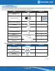
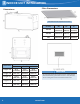
2 PACKING LIST 2-Accessories The listing below shows the accessories and parts (these may vary depending on purchase & options). Use all of the installation parts and accessories to install the system. Improper installation may result in water leakage, electrical shock, fire, and/or equipment failure. PART LOOKS LIKE QUANTITY Owner’s & Installation Manual 1 Remote Control NOTE: The wired system control functions as an IR receiver for the handheld remote.
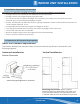
3 INDOOR UNIT INSTALLATION 3.1 Indoor Unit Parts 3.2 Installation Safety Precautions CAUTION • • Install the indoor and outdoor units, cables, and wires at least 3.2 ft (1 m) away from televisions or radios to prevent static or image distortion. Depending on the appliances, a 3.2ft (1m) distance may not be sufficient. The indoor unit must be electrically grounded per national and local electrical codes.
3 INDOOR UNIT INSTALLATION 3.3 Installation Preparation & Precautions The indoor unit should be installed in a location that meets the following requirements: √ Enough room for the installation and maintenance to be performed. √ Enough room for the refrigerant piping and drain pipe. √ On a structure that can support its weight. If the structure is too weak, the unit may fall and cause personal injury, unit and property damage, or death.
3 INDOOR UNIT INSTALLATION Filter Dimensions Dimensions Filter must meet the requirements of UL900. Model Capacity (BTU/H) Dimensions 9 Width (W) Depth (D) Thickness (t) 18K-24K 16 in 20 in .96 in (406.4 mm) (508 mm) (25.4 mm) 30K-48K 19.5 in 20 in .96 in (495.3 mm) (508 mm) (25.4 mm) 60K 23 in 20 in .96 in (584.2 mm) (508 mm) (25.
3 INDOOR UNIT INSTALLATION Installation Position Requirements Top View Side View Note on Ductwork & Connections • • • • • • • Air supply and return can be handled in one of several ways depending on which is best suited for the type of installation. Please see the dimensions on the previous page to determine duct inlet and outlet connection sizes to match the air handler.
3 INDOOR UNIT INSTALLATION 3.5 Installation Mounting Positions The unit can be installed in a Vertical (downflow or upflow) or a Horizontal (right or left) configuration. Notice • Vertical Up and Horizontal Left installation does not need to change the direction of the evaporator. 3.6 Airflow Directions 11 mrcool.
3 INDOOR UNIT INSTALLATION 3.7 Wire & Piping Connections Follow these steps to perform a vertical down and horizontal right installation: Step 1: Open the upper cover. Step 2: Open the cover of the electronic control box. Step 3: Connect the wire according to the wiring diagram. Step 4: Connect the pipes and install drainage pipes. 3.
3 INDOOR UNIT INSTALLATION 5. Unplug temperature sensors T1 and T2 from the control board. T1: Room Temperature Sensor T2: Evaporator Central Sensor Plug T2A: Evaporator Input Sensor Plug T2B: Evaporator Output Sensor Plug 7. Take out the evaporator and drain pan and rotate 180° (when a vertical down configuration is needed). 6. Remove T1 and T2 Sensor wire ties. 8. Adjust the mounting parts positioning according to the direction of the unit.
3 INDOOR UNIT INSTALLATION 10. Reinstall T1, T2, T2A, and T2B sensor plugs and electronic expansion valve (EEV) and tie up the sensor wires. The evaporator is now assembled in place. 9. Reinstall the evaporator and drain pan. NOTE The wire body needs to pass through the wire groove from the drain pan and attach to the hook on the drain pan. mrcool.
3 INDOOR UNIT INSTALLATION 11. Use cable ties to attach the room temperature sensor as shown in the figure. 13. Connect the wire according to the wiring diagram. 14. Reassemble the upper cover and reinstall the filter and filter cover plate. 12. Reinstall evaporator cover plate. 15. Connect the pipes and install drainage pipes. CAUTION FOR PIPE INSTALLATION • • • • Insulate all piping to prevent condensation, which could lead to water damage. The drainpipe is used to drain water away from the unit.
3 INDOOR UNIT INSTALLATION NOTICE ON PIPE PURCHASING Installation requires PVC pipe or other suitable material per local and national codes. These can be found at your local hardware store or dealer. WARNING • • After removing the drain pan plug(s), check the drain hole(s) to verify that the drain opening is fully clear and free of any debris. Also check to ensure no debris has fallen into the drain pan during installation that could plug the drain opening.
4 REFRIGERANT PIPING CONNECTION WARNING ON REFRIGERANT PIPING All field piping must be completed by a licensed technician and must comply with all local and national regulations. • When the air conditioner is installed in a small room, precautions must be taken to prevent the refrigerant concentration in the room from exceeding the safety limit. • When installing the refrigeration system, ensure that air, dust, moisture, or foreign substances do not enter the refrigerant circuit.
4 REFRIGERANT PIPING CONNECTION 4.2 Connecting Refrigerant Piping CAUTION Insulate both the gas and liquid piping to prevent condensation.
4 REFRIGERANT PIPING CONNECTION Step 3: Flare Pipe Ends • Place flaring tool onto the form. Proper flaring is essential to achieve an airtight seal. • Turn the handle of the flaring tool clockwise until the pipe is fully flared. • After removing burrs from cut pipe, seal the ends with PVC tape to prevent foreign materials from entering the pipe. • Sheath the pipe with insulating material. • Place flare nuts on both ends of the pipe.
4 REFRIGERANT PIPING CONNECTION NOTICE Use both a spanner and a torque wrench when connecting or disconnecting pipes to/from the unit. • After connecting the copper pipes to the indoor unit, wrap the power cable, signal cable, and the piping together with binding tape. NOTICE DO NOT intertwine or cross the signal cable with any other wiring. CAUTION Be sure to wrap insulation around the piping. Direct contact with the bare piping may result in burns or frostbite.
4 21 REFRIGERANT PIPING CONNECTION mrcool.
5 ELECTRIC HEAT KIT INSTALLATION 5-Electric Heat Kit Installation Installation Preparation NOTICE Before installation, confirm the electric auxiliary heat module and supplied accessories are present and free of damage. Do not attempt to install if damage is present. Installation must be performed by a licensed contractor. Please take necessary precautions when performing the installation.
5 ELECTRIC HEAT KIT INSTALLATION Step 3: Remove the terminal block and power wires, loosen the screws, and remove the electric auxiliary heating cover. Step 5: Tighten the mounting screws. Step 6: Wire according to the wiring nameplate. Apply Step 4: the wiring diagram to the inside cover for future Install the electric auxiliary heating assembly through reference and maintenance. the front, and note that the support assembly must Step 7: lock into the support holes in the back of the cabinet.
6 CONFIRMATION OF INDOOR UNIT 6.1 Units with Electrical Heat NOTICE • • • The electric auxiliary heating wiring diagram is packed with the accessories. If the branch circuit wire length exceeds 100ft, consult NEC 210-19a to determine maximum wire length. Use 2% voltage drop. After the electric heating wiring is connected, please confirm the following before powering on: • Check and ensure a secure connection of all wiring. • Ensure that wire size is properly selected per NEC or local codes.
6 CONFIRMATION OF INDOOR UNIT 6.4 Electric Auxiliary Heating Wiring Diagrams 25 mrcool.
6 CONFIRMATION OF INDOOR UNIT mrcool.
7 OUTDOOR UNIT INSTALLATION NOTICE Install the unit by following local switch regulations. These may differ slightly between different regions. 7.1 Outdoor Unit Location Selection Before installing the outdoor unit, you must choose an appropriate location. The following are standards to help choose an appropriate location for the unit. Meets all spatial requirements shown in installation Space Requirements above.
7 OUTDOOR UNIT INSTALLATION 7.2 Drain Fitting Installation Step 1: Find the base pan hole on the outdoor unit. Step 2: • Fit the rubber seal on the end of the drain fitting that will connect to the outdoor unit. • Insert the drain fitting into the hole in the base pan of the unit. The drain fitting will click into place. • Connect a drain hose extension (not included) to the drain fitting to redirect water from the unit during heating mode.
7 OUTDOOR UNIT INSTALLATION 7.3 Anchor Outdoor Unit The outdoor unit can be anchored to the ground or to a wall-mounted bracket with an M10 bolt. Prepare the installation base of the unit according to the dimensions below.
7 OUTDOOR UNIT INSTALLATION If installing the unit on the ground or concrete mounting platform, do the following: • • • • • • • If installing the unit on a wall-mounted bracket, do the following: Mark the positions for four expansion bolts based on the dimensions chart. Pre-Drill holes for expansion bolts. Place a nut on the end of each expansion bolt. Hammer expansion bolts into the pre-drilled holes. Remove the nuts from expansion bolts, and place the outdoor unit on bolts.
8 ELECTRICAL CONNECTIONS 8.1 Wiring Precautions WIRING WARNINGS Before performing any electrical work, read these warnings: • BEFORE PERFORMING ANY ELECTRICAL OR WIRING WORK, TURN OFF THE MAIN POWER TO THE SYSTEM. • All wiring must comply with local and national electrical codes, regulations, and must be installed by a licensed electrician. • All electrical connections must be made according to the Electrical Connection Diagram located on the panels of the indoor and outdoor units.
8 ELECTRICAL CONNECTIONS 8.3 Outdoor Unit Wiring WARNING BEFORE PERFORMING ANY ELECTRICAL OR WIRING WORK, TURN OFF THE MAIN POWER TO THE SYSTEM. Prepare the cable for connection Step 1: 1. You must first choose the right cable size. 2. Using wire strippers, strip the rubber jacket from both ends of the signal cable to reveal approximately 5.9in (15cm) of wire. 3. Strip the insulation from the ends. 4. Stranded wire requires u-lugs or ring terminals to be crimped onto the ends of the wire.
8 ELECTRICAL CONNECTIONS 8.4 Indoor Unit Wiring CAUTION • • While connecting the wires, strictly follow the wiring diagram. The refrigerant circuit can become very hot. Keep the interconnection cable away from the copper tube. Indoor Unit Wiring Step 1: Prepare the cable for connection. 1. Using wire strippers, strip the rubber jacket from both ends of the signal cable to reveal about 5.9in (15cm) of the wire. 2. Strip the insulation from the ends of the wires. Step 2: Open the front panel. 1.
8 ELECTRICAL CONNECTIONS When using a 24v thermostat, refer to the non-communicating wiring diagrams that follow: Connection Method C: The following wiring diagrams are suitable for the AHU and ODU with 24V thermostat. Non-communication scheme wiring reference • Wiring for 4H and 2C thermostat mrcool.
8 35 ELECTRICAL CONNECTIONS mrcool.
8 Optional Function Wiring: ELECTRICAL CONNECTIONS Fault Warning: Alarm Output: An alarm output (CN33) can be utilized if actions are required when a fault is present. This is a passive outlet port, so you will need to input a voltage signal. The relay is normally open for normal operation, and closed when a fault condition is active. Indoor and Outdoor Unit Communication interface Condensate Overflow Switch: The unit will accommodate a remote condensate overflow switch.
8 ELECTRICAL CONNECTIONS Humidifier Control: Control Logic Indoor Unit Connector To connect a humidifier, utilize the passive signal “WORK” output (CN23) port as well as the G and C wires on the controller, and wire the humidistat and humidifier per above wiring diagram. When the fan is running, the CN23 relay will be closed, which will allow power to the humidifier when the humidistat is below the humidity setpoint.
8 ELECTRICAL CONNECTIONS 8.6 DIP Switch Definitions mrcool.
8 ELECTRICAL CONNECTIONS Function DIP Switch Settings: Function Combination Table of SW1-1 and SW1-4: The 24V thermostat mode must refer to the following settings: SW4-1 SW4-2 SW4-3 000 is the default 000/001/010/011/100 /101/110/111, internal machines with different abilities, electric heating, and PSC classification for use. Indoor Unit Dial Code No.
8 ELECTRICAL CONNECTIONS No. Dial Code Control Scenario Function ON OFF Note 8 2 Compressor/Auxiliary heat outdoor ambient lockout The operation of heat pump is limited by the outdoor temperature, and the operation of auxiliary heat is not limited. The system makes judgments according to the following rules: [Default] Only one heat pump or auxiliary heat can be operated. The system makes judgment according to the following rules: SW2-4 and S3 need to be working together.
8 ELECTRICAL CONNECTIONS Address DIP Switch: Address dialing S1+S2: When the user uses the centralized controller, the address dialing is required.
8 ELECTRICAL CONNECTIONS Air Volume Table mrcool.
8 ELECTRICAL CONNECTIONS Air Volume Table The constant airflow volume motor is applied. Therefore, the airflow volume is constant at all ESP within the stated range. 43 mrcool.
9 SPECIFICATIONS 9-Specifications Cooling and Heating Power Specifications NOTICE Line Diameter Sizing per NFPA 70 (2020), Table 310.5 (B) (16) Based on type NM-B Romex wire. Other sizing options are possible. Consult NFPA 70 or Licensed Electrician for alternate sizing. mrcool.
10 AIR EVACUATION 10.1 Air Evacuation Preparation & Precautions NOTICE When opening valve stems, turn the hexagonal wrench until it hits against the stopper. Do not try to force the valve open further. Air and foreign matter in the refrigerant circuit can cause abnormal rises in pressure, which can damage the unit, reduce its efficiency, and cause injury. Use a vacuum pump and manifold gauge to evacuate the refrigerant circuit, removing any non-condensible gas and moisture from the system.
11 ADDING REFRIGERANT 11-Adding Refrigerant CAUTION DO NOT mix refrigerant types. Some systems require additional charging depending on pipe lengths. The standard pipe length varies according to local regulations. For example, in North America, the standard pipe length is 7.5m (25’). In other areas, the standard pipe length is 5m (16‘). The refrigerant should be charged from the service port on the outdoor unit’s low pressure valve.
12 TEST RUN CAUTION Failure to perform the test run may result in unit damage, property damage, or personal injury. 12.1 Before Test Run A test run must be performed after the entire system has been completely installed. Confirm the following points before performing the test: a) Indoor and outdoor units are properly installed. b) Piping and wiring are properly connected. c) No obstacles near the inlet and outlet of the unit that might cause poor performance or product malfunction. 5.
12 TEST RUN 12.3 24V Signal Chart Note: 1: 24V signal 0: No 24V signal *: 1 or 0 The AUU will turn off if the 24V input cannot meet the table. mrcool.
Versa Pro Central Ducted 36K-60K The design and specifications of this product and/or manual are subject to change without prior notice. Consult with the sales agency or manufacturer for details.