The Olympus Series is NOT designed for amateur installation. Installation SHOULD be performed by an authorized technician. Please read this manual carefully before installation and keep it for future reference. Installation Manual Olympus Series Single (Hyper Heat & E Star) & Multi-Zone Models The Olympus Series is NOT designed for amateur installation. Installation SHOULD be performed by an authorized technician. Please read this manual carefully before installation and keep it for future reference.
Contents ! Safety Precautions .................................. 3 1 Accessories ............................................... 5 2 Overview .................................................. 7 3 Indoor Unit Installation ...........11 1. Installation location.................................11 2. Attach mounting plate to wall...............12 3. Drill wall hole for connective piping.....13 4. Prepare refrigerant piping ....................14 5. Connect drain hose.................................15 6.
Contents 5 Refrigerant Piping Connection ...................... 27 A. Note on Pipe Length ............................................................. 27 B. Connection Instructions –Refrigerant Piping .................. 27 1. Cut pipe .............................................................................. 27 2. Remove burrs ................................................................... 28 3. Flare pipe ends ................................................................. 28 4. Connect pipes ..
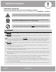
Safety Precautions Safety Precautions Read Before Installation ! Incorrect installation may cause serious damage or injury. The seriousness of potential damage or injuries is classified as either a WARNING or CAUTION. This symbol indicates ignoring instructions may cause death or serious injury. WARNING This symbol indicates that ignoring instructions may cause moderate injury to your person, damage to your unit, or other property.
Safety Precautions 7. You must use an independent circuit to supply power. Do not connect other appliances to the same circuit. Insuficient electrical capacity or defects in electrical work can cause electrical shock or fire. 8. For all electrical work, fuse the specified cables. Connect cables tightly, and clamp them securely to prevent external forces from damaging the terminal. Improper electrical connections may overheat, causing fire and/or electrical shock. 9.
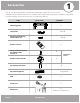
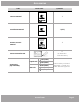
Accessories 1 Safety Precautions The air conditioning system includes the following accessories. Use all of the installation parts and accessories to install the air conditioner. Improper installation may result in water leakage, electrical shock, fire, or equipment failure. PART LOOKS LIKE... QUANTITY Mounting plate 1 Clip anchor 5 or 8 Mounting plate fixing screw ST3.9 X 25 5 or 8 Remote control 1 Fixing screw for remote controller holder ST2.
Accessories PART LOOKS LIKE... QUANTITY Please read this manual carefully before installation and keep it for future reference. Owner’s Manual 1 Owner’s Manual Olympus Series For more details visit www.MrCool.com Please read this manual carefully before installation and keep it for future reference. Installation Manual 1 (this) Installation Manual Olympus Series Please read this manual carefully before installation and keep it for future reference.
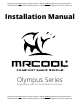
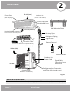
2 Overview Air inlet (rear) Front Panel Indoor Unit (Interior / Air Handler) (with display) Smart Controller Module USB Port Wall Mounting Plate Air outlet (bottom) Vertical Airflow Louver Drainage Pipe Horizontal Airflow Grill (inside) Refrigerant Piping Signal Cable Fresh Air Filter (on front of main filter in Specified Units) Remote Control Air inlet (rear) Air inlet (side) Remote Holder Outdoor Unit Power Cable Air outlet Signal Cable Connection from Indoor Unit Refrigerant Pipe Connect
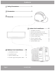
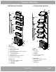
Overview - Multi-Zone Wall-Mounted Handlers Ceiling Ducted Handlers 5-Zone 5-Zone 4-Zone 4-Zone 3-Zone 3-Zone 2-Zone 2-Zone Fig. 2.2 Indoor unit 1. Panel frame 2. Rear air intake grille 3. Front panel 4. Air Purifying filter & Air filter (behind) 5. Horizontal louver 6. LCD display window 7. Vertical louver 8. Manual control button (behind) 9. Remote control holder Fig. 2.3 Indoor unit 1. Air outlet 2. Air inlet 3. Air filter 4. Electric control cabinet 5. Wire controller Outdoor unit 6.
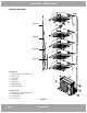
Overview - Multi-Zone Cassette Handlers 5-Zone 4-Zone 3-Zone 2-Zone Indoor unit 1. Drain pump (from indoor unit) 2. Drain hose 3. Air outlet 4. Air inlet 5. Air-in grill 6. Display panel 7. Remote control Outdoor unit 8. Refrigerant connecting pipe 9. Connective cable 10. Stop valve 11. Fan hood Page 9 Fig. 2.4 mrcool.
Overview - Specifications Table 2.1 Indoor units that can be used in combination Number of connected units 1-5 units Compressor stop/start frequency Stop time 3 min or more voltage fluctuation within ±10% of rated voltage voltage drop during start within ±15% of rated voltage interval unbalance within ±3% of rated voltage Power source voltage Table 2.2 Unit: ft/m 2 ZONE 3 ZONE 4 ZONE 5 ZONE Max. length for all rooms 98.4ft/30m 147.6ft/45m 196.8ft/60m 246ft/75m Max.
Installation Summary - Indoor Unit Indoor Unit Installation Installation Instructions – Indoor Unit DO NOT install unit in the following locations: Near any source of heat, steam, or combustible gas PRIOR TO INSTALLATION: Before installing the indoor unit, refer to the label on the product box to make sure that the model number of the indoor unit matches the model number of the outdoor unit.
Indoor Unit Installation Refer to the following diagram to ensure proper distance from walls and ceiling: Minimum Ceiling Clearance is 15cm (5.9in) >12cm (4.75in) >12cm (4.75in) For Ceilings GREATER Than 9 Foot, Suggested Floor Clearance is 230cm(90.55in) For Ceilings LESS Fig. 3.1 Than 9 Foot, Suggested Floor Clearance is 200cm(78.55in) Step 2: Attach mounting plate to wall Step 3: Drill wall hole for connective piping The mounting plate is the device on which you will mount the indoor unit .
Indoor Unit Installation Indoor Wall Outdoor 0.2 - 0.3in (5 - 7 mm) 4.3in/11mm Right rear side refrigerant pipe hole Left rear side refrigerant pipe hole 2.6in/65mm 2.6in/65mm Series 9K Models Fig.3.2 MOUNTING PLATE DIMENSIONS 4.3in/11mm Different models have different mounting plates.
Indoor Unit Installation 3. Use scissors to cut down the length of the Step 4: Prepare refrigerant piping The refrigerant piping is inside an insulating sleeve attached to the back of the unit. You must prepare the piping before passing it through the hole in the wall. Refer to the Refrigerant Piping Connection section of this manual for detailed instructions on pipe flaring and flare torque requirements, technique, etc. insulating sleeve to reveal about 6in (15cm) of the refrigerant piping.
Indoor Unit Installation Make sure there are NO kinks or dents in the hose to ensure proper drainage. Step 5: Connect drain hose By default, the drain hose is attached to the left-hand side of unit (when you’re facing the back of the unit). However, it can also be attached to the right-hand side. 1. To ensure proper drainage, the drain hose must exit the unit on the same side as the refrigerant piping. 2. Wrap the connection point firmly with Teflon tape Fig. 3.
Indoor Unit Installation BEFORE PERFORMING ELECTRICAL WORK, READ THESE REGULATIONS 1. All wiring must comply with local and national electrical codes, and must be installed by a licensed electrician. 2. All electrical connections must be made according to the Electrical Connection Diagram located on the panels of the indoor and outdoor units. 3. If there is a serious safety issue with the power supply, stop work immediately.
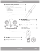
Indoor Unit Installation Step 6: Connect signal cable TAKE NOTE OF FUSE SPECIFICATIONS The signal cable enables communication between the indoor and outdoor units and provides power to the indoor unit. A 16 gauge AWG signal cable (H07RN-F) is provided for the unit. The tables below are for reference. The air conditioner’s circuit board (PCB) is designed with a fuse to provide overcurrent protection. The specifications of the fuse are printed on the circuit board, such as: T3.15A/250VAC, T5A/250VAC, etc.
Indoor Unit Installation 6. Feed the signal wire through this slot, from the DO NOT INTERTWINE SIGNAL CABLE WITH OTHER WIRES 7. Facing the front of the unit, match the wire While bundling these items together, do not intertwine or cross the signal cable with any other wiring. back of the unit to the front. colors with the labels on the terminal block, connect the u-lug and firmly screw each wire to its corresponding terminal. 2.
Indoor Unit Installation If refrigerant piping is already embedded in the wall, do the following: 1. Hook the top of the indoor unit on the upper hook of the mounting plate. 2. Use a bracket or wedge to prop up the unit, giving you enough room to connect the refrigerant piping, signal cable, and drain hose. Refer to Fig. 3.9 for an example. Connect drain hose and refrigerant piping (refer to Refrigerant Piping Connection section of this manual for instructions).
4 Indoor Unit Installation Outdoor Unit Installation Installation Instructions – Outdoor Unit 24in (60cm) above Step 1: Select installation location Before installing the outdoor unit, you must choose an appropriate location. The following standards will help you choose an appropriate location.
Outdoor Unit Installation IN COLD CLIMATES Wind Baffle In cold climates, make sure that the drain hose is as vertical as possible to ensure swift water drainage. If water drains too slowly, it can freeze in the house and flood the unit. Strong wind Fig. 4.3 Step 2: Install drain joint Base pan hole of outdoor unit Heat pump units require a drain joint. Before bolting the outdoor unit in place, you must install the drain joint at the bottom of the unit.
Outdoor Unit Installation Step 3: Anchor outdoor unit - single-zone (Hyper Heat & E Star) A Air Inlet D H Air Inlet B Air Outlet Fig. 4.6 W UNIT MOUNTING DIMENSIONS The following is a list of different outdoor unit sizes and the distance between their mounting feet. Prepare the installation base of the unit according to the dimensions below. Outdoor Unit Dimensions (inches) Mounting Dimensions (inches) Width (A) Width (W) x Height (H) x Depth (D) Depth (B) O-HH-09-HP-C-230 31.50 x 21.81 x 13.
Outdoor Unit Installation Step 3: Anchor outdoor unit - Multi-Zone W H H W Fig. 4.7 A D B Fig. 4.9 Fig. 4.8 Outdoor Unit Dimensions (inches) Width (W) x Height (H) x Depth (D) Mounting Dimensions (inches) Width (A) Depth (B) MULTI2-18HP230V1 33.27 x 27.6 x 14.3 (inches) 21.26 in. 13.8 in. MULTI3-27HP230V1 37.2 x 31.9 x 16.4 (inches) 26.5 in. 15.87 in. MULTI4-36HP230V1 37.2 x 31.9 x 16.4 (inches) 26.5 in. 15.87 in. MULTI5-48HP230V1 25.2 in. 15.9 in. 37.5 x 52.5 x 16.
Outdoor Unit Installation Step 4: Connect signal and power cables wall-mounted installation continued 6. Check that the mounting brackets are level. 7. Carefully lift unit and place its mounting feet on brackets. BEFORE PERFORMING ELECTRICAL WORK, READ THESE REGULATIONS 1. All wiring must comply with local and national electrical codes, and must be installed by a licensed electrician. 8. Bolt the unit firmly to the brackets.
Outdoor Unit Installation PAY ATTENTION TO LIVE WIRE BEFORE PERFORMING ANY ELECTRICAL OR WIRING WORK, TURN OFF THE MAINPOWER TO THE SYSTEM. 1. Prepare the cable for connection: ALL WIRING MUST PERFORMED STRICTLY IN ACCORDANCE WITH THE WIRING DIAGRAM LOCATED INSIDE THE OUTDOOR UNIT’S WIRE COVER. USE THE RIGHT CABLE • Outdoor power cable is not provided • See table below for gauge requirements 2. Unscrew the electrical wiring cover and remove it.
Outdoor Unit Installation Wiring Diagram CAUTION Connect the power and communication cables to the terminals as identified with their respective matched numbers on the terminal block of indoor and outdoor units. For example, see the following US models: Terminal L1(A) of outdoor must connect with terminal L1 on the indoor unit. 2-Zone models: 4-Zone models: 3-Zone models: 5-Zone models: mrcool.
65 Outdoor Unit Installation Refrigerant Piping Connection Refrigerant Piping Connection NOTE ON PIPE LENGTH The length of refrigerant piping will affect the performance and energy efficiency of the unit. Nominal efficiency is tested on units with a pipe length of 16.5ft (5 meters). Refer to the table below for specifications on the maximum length and drop height of piping. Maximum Length and Drop Height of Refrigerant Piping per Unit Model Model Capacity (BTU/h) Max.
Refrigerant Piping Connection Flare nut DO NOT DEFORM PIPE WHILE CUTTING Be extra careful not to damage, dent, or deform the pipe while cutting. This will drastically reduce the heating efficiency of the unit. Copper pipe Step 2: Remove burrs Fig. 5.3 Burrs can affect the air-tight seal of refrigerant piping connection. They must be completely removed. 4. Remove PVC tape from ends of pipe when ready to perform flaring work. 1. Hold the pipe at a downward angle to prevent burrs from falling into the pipe.
Refrigerant Piping Connection 6. Place flaring tool onto the form. Step 4: Connect pipes 7. Turn the handle of the flaring tool clockwise until When connecting refrigerant pipes, be careful not to use excessive torque or to deform the piping in any way. You should first connect the low-pressure pipe, then the high-pressure pipe. the pipe is fully flared. 8. Remove the flaring tool and flare form, then inspect the end of the pipe for cracks and even flaring. Table 5.
Refrigerant Piping Connection Instructions for Connecting Piping to Indoor Unit 1. Align the center of the two pipes that you will connect. See Fig. 5.7. Indoor unit tubing Flare nut Valve cover Pipe Fig. 5.9 Fig. 5.7 2. Tighten the flare nut as tightly as possible by hand. 3. Using an adjustable wrench, grip the nut on the unit tubing. 4. While firmly gripping the nut on the unit tubing, use a torque wrench to tighten the flare nut according to the torque values in Table 5.2.
6 Air Evacuation 1. Connect the charge hose of the manifold gauge Preparations and Precautions Air and foreign matter in the refrigerant circuit can cause abnormal rises in pressure, which can damage the air conditioner, reduce its efficiency, and cause injury. Use a vacuum pump and manifold gauge to evacuate the refrigerant circuit, removing any non-condensable gas and moisture from the system. Evacuation should be performed upon initial installation and when unit is relocated.
Air Evacuation Low Pressure Main Valve High Pressure Main Valve “Suction” Low Pressure “Liquid” High Pressure Flare nut Valve stem Cap Valve body Fig. 6.2 Fig. 6.3 Note on Adding Refrigerant Some systems require additional charging depending on pipe lengths. The standard pipe length varies according to local regulations. For example, in North America, the standard pipe length is 25ft (7.5m). In other areas, the standard pipe length is 16ft (5m).
Refrigerant Piping Connection System Leak and Checks Electrical Gas Leak Checks Electrical Safety Checks WARNING – RISK OF ELECTRIC SHOCK After installation, confirm that all electrical wiring is installed in accordance with local and national regulations, and according to the Installation Manual. BEFORE TEST RUN Check Grounding Work Measure grounding resistance by visual detection and with grounding resistance tester. Grounding resistance must be less than 4.
System Leak Checks Self Correction Function (Multi-Zone Models Only) Multi-Zone units have a self check function for wiring to piping association errors. Press the "check switch" on the outdoor unit PCB board for 5 seconds until LED displays "CE". Approximately 5-10 minutes after the switch is pressed, the "CE" will disappear when the wiring and piping are reassociated and the error is corrected.
Test Run Refrigerant Piping Connection 8 Before Test Run List of Checks to Perform Only perform test run after you have completed the following steps: • Electrical Safety Checks – Confirm that the electrical system is safe and operating properly No electrical leakage Unit is properly grounded • Gas Leak Checks – Check all flare nut connections and confirm that the system is not leaking All electrical terminals properly covered • Confirm that gas and liquid (high and low pressure) valves are fully open
Testing DOUBLE-CHECK PIPE CONNECTIONS During operation, the pressure of the refrigerant circuit will increase. This may reveal leaks that were not present during your initial leak check. Take time during the Test Run to double-check that all refrigerant pipe connection points do not have leaks. Refer to Gas Leak Check section for instructions. 5. After the Test Run is successfully complete, and you confirm all check points in List of Checks to Perform have PASSED, do the following: a.
Refrigerant Piping Connection EU Disposal Guidelines 9 This appliance contains refrigerant and other potentially hazardous materials. When disposing of this appliance, the law requires special collection and treatment. DO NOT dispose of this product as household waste or unsorted municipal waste. When disposing of this appliance, you have the following options: • Dispose of the appliance at a designated municipal electronic waste collection facility.
Olympus Series Single (Hyper Heat & E Star) & Multi-Zone Models ELECTRICIAN and/or HVAC TECHNICIAN: LICENSE #: INSTALLATION DATE: INSTALLATION LOCATION: SERIAL NUMBER: The design and specifications of this product and/or manual are subject to change without prior notice. Consult with the sales agency or manufacturer for details.