The Olympus Series is NOT designed for amateur installation. Installation SHOULD be performed by an authorized technician. Please read this manual carefully before installation and keep it for future reference. User Manual Olympus Series Single (Hyper Heat & Energy Star) & Multi-Zone Models The Olympus Series is NOT designed for amateur installation. Installation SHOULD be performed by an authorized technician. Please read this manual carefully before installation and keep it for future reference.
Read Before Operation This appliance can be used by children aged 8 years and above and persons with reduced physical, sensory or mental capabilities or lack of experience and knowledge if they have been given supervision or instruction concerning use of the appliance in a safe way and understand the hazards involved. Children should not play with the appliance. Cleaning and user maintenance should not be made by children without supervision.
Contents ! Safety Precautions 1 Overview Warnings ................................................................................................................................. Cautions .................................................................................................................................. Parts Diagram (Overview) .................................................................................................... Multi-Zone Diagram (Wall-Mounted Indoor Handlers) ...........
Safety Precautions Safety Precautions ! Read Before Using Incorrect usage may cause serious damage or injury. The seriousness of potential damage or injuries is classified as either a WARNING or CAUTION. This symbol indicates ignoring instructions may cause death or serious injury. WARNING This symbol indicates that ignoring instructions may cause moderate injury to your person, damage to your unit, or other property. CAUTION This symbol indicates that you should NEVER perform the indicated action.
Safety Precautions CAUTION DO NOT touch switches with a wet hand. It may cause electric shock. DO NOT use the device for any other purpose than the intended use. DO NOT expose plants or animals directly to the airflow. DO NOT place food, precision instruments, plants, animals, paint, etc. on the unit. DO NOT clean the interior unit with water. DO NOT use combustible cleaning agents as this could cause fire or deformation. DO NOT place burning objects near the unit or directly in the path of its airflow.
1 Safety Precautions Overview Air inlet (rear) Front Panel Indoor Unit (Interior / Air Handler) (with display) Smart Controller Module USB Port Wall Mounting Plate Air outlet (bottom) Vertical Airflow Louver Drainage Pipe Horizontal Airflow Grill (inside) Refrigerant Piping Signal Cable Fresh Air Filter (on front of main filter in Specified Units) Remote Control Air inlet (rear) Air inlet (side) Remote Holder Outdoor Unit Power Cable Air outlet Signal Cable Connection from Indoor Unit Refr
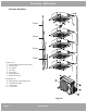
Overview - Multi-Zone Wall-Mounted Handlers Ceiling Ducted Handlers 5-Zone 5-Zone 4-Zone 4-Zone 3-Zone 3-Zone 2-Zone 2-Zone Fig. 2.1 Indoor unit 1. Panel frame 2. Rear air intake grille 3. Front panel 4. Air Purifying filter & Air filter (behind) 5. Horizontal louver 6. LCD display window 7. Vertical louver 8. Manual control button (behind) 9. Remote control holder Outdoor unit 10. Drain hose, refrigerant connecting pipe 11. Connective cable 12. Stop valve 13. Fan hood Fig. 2.2 Indoor unit 1.
Overview - Multi-Zone Cassette Handlers 5-Zone 4-Zone 3-Zone 2-Zone Indoor unit 1. Drain pump (from indoor unit) 2. Drain hose 3. Air outlet 4. Air inlet 5. Air-in grill 6. Display panel 7. Remote control Outdoor unit 8. Refrigerant connecting pipe 9. Connective cable 10. Stop valve 11. Fan hood Fig. 2.4 Page 7 mrcool.
Overview - Display 1 2 4 turbo defrost run timer 3 5 fig. 1.2 Display (on front panel of indoor unit) see fig. 1.2 1. Digital Display: Displays the Temperature Setting when the air conditioner is operational. Displays the Room Temperature when in FAN mode. Displays Self-Diagnostic Codes: Displays “ON” for three seconds when the Timer is ON and/or Fresh, Swing, Turbo or Silence feature is activated. Displays “OF” for three seconds when the Timer is switched OFF.
Safety Precautions Operating Instructions Cooling Operation Room Temperature Outdoor Temperature 2 Heating Operation Drying Operation (17°C~32°C) 62°F~90°F (0°C~50°C) 32°F~122°F 5°F~122°F / -15°C~50°C (For the models with low ambient cooling system) (0°C~30°C) 32°F~86°F (10°C~32°C) 50°F~90°F (-15°C~30°C) 5°F~86°F (0°C~50°C) 32°F~122°F NOTE: 1. Optimum performance will be achieved within these operating temperatures.
Operating Instructions Airflow Directional Control · Adjust the airflow direction properly. Otherwise, it might cause discomfort or uneven room temperatures. · Adjust the vertical louver using the remote. · Adjust the horizontal louver manually. Adjust Vertical (Up / Down) Air Flow using Vertical Louver (fig2.2): Perform this function while the unit is in operation. Use the remote control to adjust the Vertical Louver / Vertical Air Flow direction.
Operating Instructions How the air conditioner works Basic Operation MODEs: AUTO / COOL / DRY / HEAT (Model dependent). 7 hours timer OFF SLEEP operation Auto Operation: When you set the air conditioner in AUTO mode, it will automatically select cooling, heating or fan-only operation depending on set temperature and room temperature. The unit will control the room temperature automatically, according to the temperature point you set.
Operating Instructions Special Functions Refrigerant Leakage Detection (optional): When refrigerant leakage is detected, the indoor unit will display “EC” code or flash LEDs, depending on the model. Louver Angle Memory Function (optional): Within the scope of the safe operation angle, the horizontal louver angle is memorized and will return to the position last selected by the user. If it exceeds the safe operation angle, it will default within the safe operation range.
Operating Instructions Care and Maintenance 3 Before maintenance turn the power off to the unit. Then, disconnect the power to the circuit at the breaker. 1 Cleaning the Unit: Wipe the unit with a soft dry cloth. If the unit is very dirty, wipe it with a cloth soaked in warm water. Do not use bleach or abrasives. 2 Cleaning the Air Filter and Air Freshener: A clogged air filter can greatly reduce the heating and cooling efficiency of this unit. It is recommended to clean the unit every 2 weeks.
Care and Maintenance Before maintenance turn the power off to the unit. Then, disconnect the power to the circuit at the breaker. Cleaning the Air Filter continued: 7. Re-fit air filter back into the unit by reversing steps 2 and 3 - gently pushing top up into the unit and then lowering the bottom into place. 8. Close the front panel. Make sure that buckles are fully fit and the panel is completely closed.
Troubleshooting The following events may occur during normal operation, and may not indicate malfunction. Symptom Cause To prevent blowout of the fuse, the compressor will not operate while Operation is the protection circuit is working for about 3 minutes after sudden OFF--ON delayed after restart operation of the power supply.
Troubleshooting Before you call to request service assistance, troubleshoot a problem by performing the following checks: Symptom Diagnostic -- Is there a power failure? Unit will not operate -- Has a switch been turned off, a circuit breaker tripped or a fuse blown? -- Is the timer operating? -- Are the batteries used in the remote controller exhausted? -- Are the batteries used in the remote controller loaded properly? -- Are the air filters dirty? -- Is air flow unrestricted in & out of indoor & outdoor
Troubleshooting Indoor Unit Error Display Operation LED Timer LED Display 1 time X E0 Indoor unit EEPROM parameter error 2 times X E1 Indoor / outdoor units communication error 3 times X E2 Zero-crossing signal detection error 4 times X E3 Indoor fan speed has been out of control 5 times X E4 Indoor room temperature sensor T1 open circuit or short circuit 6 times X E5 Evaporator coil temperature sensor T2 open circuit or short circuit 7 times X EC Refrigerant leakage detection
Olympus Series Single (Hyper Heat & Energy Star) & Multi-Zone Models ELECTRICIAN and/or HVAC TECHNICIAN: LICENSE #: INSTALLATION DATE: INSTALLATION LOCATION: SERIAL NUMBER: The design and specifications of this product and/or manual are subject to change without prior notice. Consult with the sales agency or manufacturer for details.