
Installation Manual

Page 25 mrcool.com
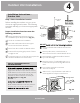
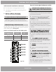
Outdoor Unit Installation
PAY ATTENTION TO LIVE WIRE
While crimping wires, make sure you clearly
distinguish the Live (“L”) Wire from other wires.
ALL WIRING MUST PERFORMED STRICTLY
IN ACCORDANCE WITH THE WIRING
DIAGRAM LOCATED INSIDE THE OUTDOOR
UNIT’S WIRE COVER.
1.
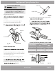
Prepare the cable for connection:
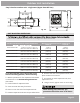
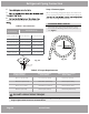
USE THE RIGHT CABLE
Rated Current
of Appliance (A)
Nominal
Cross-Sectional
Area (mm²)
0.75
1
1.5
2.5
4
> 3 and 6
> 6 and
10
> 10 and
16
> 16 and
25
> 25 and
32
> 32 and
40 6
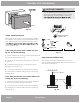
BEFORE PERFORMING ANY ELECTRICAL
OR WIRING WORK, TURN OFF THE
MAINPOWER TO THE SYSTEM.
Other Regions
North America
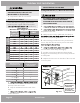
2.
3.
and place it to the side.
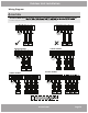
4. Match the wire colors / labels with the labels on
wire to its corresponding terminal.
5. After checking to make sure every connection is
secure, loop the wires around to prevent rain water
6.
unit. Screw the cable clamp down tightly.
7. Insulate unused wires with PVC electrical tape.
Arrange them so that they do not touch any electrical
or metal parts.
8. Replace the wire cover on the side of the unit, and
screw it in place.
•
Outdoor power cable is not provided
•
See table below for gauge requirements
•
Indoor power / signal cable from outdoor
Installation)
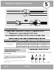
a.
from both ends of cable to reveal about 1.57 in
(40 mm) of the wires inside.
b.
Strip the insulation from the ends of the
wires.
c.
ends of the wires.
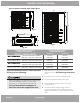
Fig. 4.11
Conduit Panel
Communication
Cable
Power
Supply Cord
Outdoor Unit
Wiring Diagram
is located on
the inside of the
wire cover on
the outdoor unit.
Appliance
Amps (A)
Hyper-Heat
Condensers
Multi-Zone
Condensers
AWG
15
15
20
18K
12K
9K
Model
Capacity
(BTU/hr)
Minimum Wire Gauge for Power Cables
MCA MOP
Min. Pref.
14
14
14
14
14
12
10
12
15
2524K 12 1018
159K 14 149
15
25
3024K
18K
12K 14
12
10
14
10
8
9
18
20
2518K (2-Zone) 12 1018
3527K (3-Zone) 10 825
4536K (4-Zone) 8 630
5048K (5-Zone) 8 635
E-Star
Condensers