
Install Manual
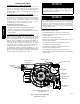
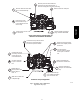
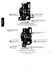
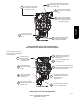
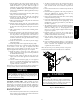
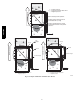
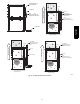
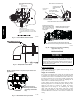
Table Of Contents
12
CONDENSATE TRAP
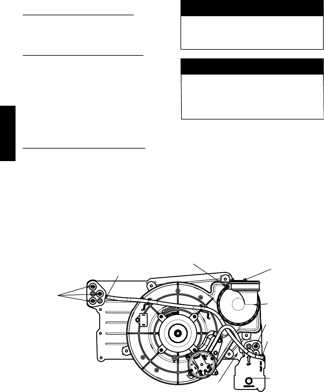
Condensate Trap -- Upflow Orientation
When the furnace is installed in the upflow position, it is not
necessary to relocate the condensate trap or associated tubing.
Refer to Fig. 8 for upflow condensate trap information. Refer to
Condensate Drain section for information how to install the
condensate drain.
Condensate Trap -- Downflow Orientation.
When the furnace is installed in the downflow position, the
condensate trap will be initially located at the upper left corner of
the collector box, as received from the factory . See the top image
in Fig. 9. When the furnace is installed in the downflow
orientation, the condensate trap must be relocated for proper
condensate drainage. See the bottom image in Fig. 9.
To Relocate the Condensate Trap:
S Or i ent the furna ce in the downflow posi tion.
S Fig. 9 shows the condensa te trap and tubing befor e and af t er
rel oca t ion. Refe r to Fig. 9 to begin the trap conve rs i on.
S Refe r to Condens at e Dra i n sec ti on for infor m at i on how to inst al l the
condens at e dra in.
Condensate Trap -- Horizontal Orientation.
Whe n the fur nac e is ins ta ll ed in the hori zont al r i ght posit i on, the
condens at e trap wil l be initially located at the bottom of the collector
box, as received from the factory. See the top image in Fig. 10.
When the furnace is installed in the horizontal left position, the
condens at e trap wil l be initially located at the top of the collector box,
as received from the factory. See the top image in Fig. 11. In both
cas es the trap must be re posi t ione d on the coll e ct or box for prope r
condens at e dra ina ge. See the bottom ima ges in Fig. 10 and 11.
A field--supplied, accessory Horizontal Installation Kit (trap
grom met ) is require d for all dir ec t--vent horizont al i nst alla ti ons (onl y).
The kit contai ns a rubber cas ing grom met des igne d to sea l betwe en
the fur nac e cas ing and the conde nsa t e tra p. See Fig. 17.
The field--supplied, accessory horizontal drain trap grommet is
ONLY REQUIRED FOR DIRECT VENT APPLICATIONS.
It it NOT required for applications using single-- pipe or
ventilated combustion air venting.
NOTICE
The condensate trap extends below the side of the casing in
the horizontal position. A minimum of 2-- in. (51 mm) of
clearance is required between the casing side and the furnace
platform for the trap to extend out of the casing in the
horizontal position. Allow at least 1/4 --in. per foot (20 mm
per meter) of slope down.
NOTICE
To Relocate the Condensate Trap:
S Rem ove the knockout in the casi ng for the condens at e tr ap.
S Inst al l the grom met in the cas ing when re quir ed for dire ct--vent
horiz onta l applic at ions .
S Orient the furnace in the desired position.
S Al l ow for 2 in. (51 mm) of cl ea ra nce undernea th the furnac e for the
condens at e tr ap and dra in line.
S Fig. 10 shows the condensa te trap and tubing befor e and af t er
rel oca tion in the hori zont a l ri ght posi t ion.
S Fig. 11 shows the condens at e tr ap and tubing befor e and af te r
rel oca tion in the hori zont a l le ft posit ion.
S Refe r to the appropr ia t e fi gure to begin the tra p conver s ion.
S Refe r to Condens at e Dra i n sec ti on for infor m at i on how to inst al l the
condens at e dra in.
Condensate Trap
Relief Port
Collector Box
Plugs
Pressure Switch
Port
Condensate Trap
Outlet
Condensate Trap
Relief Port
Collector Box
Plug
Vent Elbow
Vent Elbow Clamp
Vent Pipe Clamp
UPFLOW TRAP CONFIGURATION
1 & 2 Stage Units
A11307
Fig. 8 -- Upflow Trap Configuration
(Appearance may vary)
PG95SAS