
Install Manual
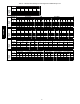
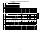


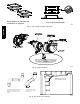
Table Of Contents
43
3. Chamfer outside edge of pipe for better distribution of
primer and cement.
4. Clean and dry all surfaces to be joined.
5. Check dry fit of pipe and mark insertion depth on pipe.
6. Insert the vent pipe into the vent elbow.
7. Torque clamp on vent elbow 15 lb-- in.
8. Torque clamp on vent coupling 15 lb--in.
9. Insert the combustion air pipe into the adapter.
10. Pilot drill a screw hole through the adapter into the combus-
tion air pipe and secure the pipe to the adapter with sheet
metal screws. DO NOT DRILL INTO POLYPROPYL-
ENE VENT PIPES. Use an optional accessory vent coup-
ling, if needed.
11. Seal around the combustion air pipe with silicone or foil
tape. SILICONE SEALERS MAY NOT BE APPRO-
PRIATE FOR POLYPROPYLENE VENT SYSTEMS.
SEE POLYPROPYLENE VENT SYSTEM MANU-
FACTURER’S INSTRUCTIONS.
12. After pipes have been cut and pre-- assembled, apply gener-
ous layer of cement primer to pipe fitting socket and end of
pipe to insertion mark. Quickly apply approved cement to
end of pipe and fitting socket (over primer). Apply cement
in a light, uniform coat on inside of socket to prevent
buildup of excess cement. Apply second coat. DO NOT
CEMENT POLYPROPYLENE FITTINGS.
13. While cement is still wet, twist pipe into socket with 1/4--in.
turn. Be sure pipe is fully inserted into fitting socket.
14. Wipe e xce ss ce ment f rom joi nt. A conti nuous bead of c ement
will be vis i ble ar ound peri met er of a prope rl y ma de joi nt.
15. Handl e pipe joi nts ca r ef ull y until cem ent sets .
16. Hori zont al portions of the venting sys t em shall be supporte d to
preve nt saggi ng. Spac e combus t ion air piping and vent piping
hanger s as show n in Tabl e 13. Support pipes us ing pe rf ora te d
me ta l ha ngi ng str ap or c omm er ci ally ava i la ble hangers or
str aps des i gned to support plast i c pipe.
17. Slope the vent and combus ti on air pi pi ng downwar d tow ards
furnace. A minimum slope of at least 1/4-in. (6 mm) per linear
ft.(1- in (25 mm) pe r 4 ft .( 1.2 M)) wit h no sags betwe en
hanger s is re quir e d. See Cauti on Box below.
FURNACE RELIABILITY HAZARD
Failure to follow this caution may result in nuisance short
cycling, frozen vent termination, and/or no heat.
Slope the vent and combustion air piping downward towards
furnace a minimum of 1/4--in. (6 mm) per linear ft. of pipe.
CAUTION
!
18. Complete the vent and combustion air pipe installation by con-
necting the concentric vent or by installing the required termin-
ati on elbows as shown in Figs. 51, 52 a nd 53.
For Ventilated Combustion Air Termination, See Fig. 54.
19. Use appropr i at e methods to sea l openi ngs wher e com bust i on
air pipe and vent pipe pass thr ough roof or si dewall.
CARBON MONOXIDE POISONING HAZARD
Failure to follow this warning could result in personal injury
or death.
DO NOT use cement to join polypropylene venting systems.
Follow the polypropylene venting system manufacturer’s
instructions for installing polypropylene venting systems.
!
WARNING
Table 13 – Hanger Spacing
Diameter
Material
PVC Sch 40 SDR 21 & 26 ABS CPVC Polypropylene
1 ½ --- i n . 3 --- f t . 2 ½ --- f t . 3 --- f t . 3 --- f t . 3.25--- ft.
3 8 --- m m 914--- mm 762--- mm 914--- mm 914---mm 1000 mm
2 --- i n . 3 --- f t . 3 --- f t . 3 --- f t . 3 --- f t . 3.25--- ft.
5 1 --- m m 914--- mm 914--- mm 914--- mm 914---mm 1000 mm
2 ½ --- i n . 3 1 / 2 --- f t . 3 --- f t . 3 1 / 2 --- f t . 3 1 / 2 --- f t . 3.25--- ft.
6 4 --- m m 1067--- mm 914---mm 1067---mm 1067--- mm 1000 mm
3 --- i n . 3 1 / 2 --- f t . 3 --- f t . 3 1 / 2 --- f t . 3 1 / 2 --- f t . 3.25--- ft.
7 6 --- m m 1067--- mm 914---mm 1067---mm 1067--- mm 1000 mm
4 --- i n . 4 --- f t . 3 1 / 2 --- f t . 4 --- f t . 4 --- f t . 3.25--- ft.
102--- mm 1219---mm 1067--- mm 1219---mm 1219--- mm 1000 mm
PG95SAS