
Install Manual


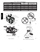

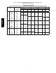
Table Of Contents

64
b. Turn gas valve ON/OFF switch to OFF.
c. Remove manifold pressure tap plug from gas valve.
d. Connect a water column manometer or similar device to
manifold pressure tap.
e. Turn gas valve ON/OFF switch to ON.
f. Manually close blower door switch.
g. Jumper R and W thermostat connections on control to start
furnace. See Fig. 37.
h. Remove regulator adjustment cap from gas valve pressure
regulator and turn adjusting screw (3/16 or smaller flat--
tipped screwdriver) counterclockwise (out) to decrease in-
put rate or clockwise (in) to increase input rate. See Fig.
57.
For 40,000 BTUH models through 120,000 BTUH models:
DO NOT set manifold pressure less than 2.8 --in. w.c. (697 Pa)
or more than 3.8 in. w.c. (947 Pa) for natural gas. If required
manifold pressure is outside this range, change main burner
orifices to obtain manifold pressure in this range.
NOTICE
FURNACE DAMAGE HAZARD
Failure to follow this caution may result in reduced furnace
life.
The 26,000 BTUH model has a lower nominal manifold
pressure than other models. Do not adjust the natural gas
manifold pressure above 1.8-- in. W.C.
The 26,000 BTUH model can be identified by the green
label affixed to the solenoid of the gas valve.
Refer to the Adjustment section for setting the manifold
pressure.
USE TABLE 22 WHEN ADJUSTING 26,000 BTUH
MODEL MANIFOLD PRESSURE.
CAUTION
!
i. When correct input is obtained, replace cap that conceals
gas valve regulator adjustment screws. Main burner flame
should be clear blue, almost transparent See Fig. 65.
j. Remove jumper R to W.
2. Verify natural gas input rate by clocking meter.
NOTE: Contact your HVAC distributor or gas supplier for metric
gas meter Tables, if required.
a. Turn off all other gas appliances and pilots served by the
meter.
b. Jumper R to W.
c. Run furnace for 3 minutes.
d. Measuretime(in sec)forgasmetertocompleteonerevolu-
tion and note reading. The 2 or 5 cubic feet dial provides
a more accurate measurement of gas flow.
e. Refer to Table 20 for cubic ft. of gas per hr.
f. Multiply gas rate cu ft./hr by heating value (Btuh/cu ft.) to
obtain input rate.
g. If clocked rate does not match required input from Step 1,
increase manifold pressure to increase input or decrease
manifoldpressureto decreaseinput.Repeatsteps b through
e of Step 1 until correct heat input is achieved. Re--install
regulator seal cap on gas valve.
3. Restore furnace to normal operating condition.
a. Turn gas v alve ON/OFF switch to OFF.
b. Remove water column manometer or similar device from
manifold pressure tap.
c. Replace manifold pressure tap plug to gas valve.
d. Turn gas v alve ON/OFF switch to ON.
e. Check for gas leaks and verity furnace operation.
FIRE HAZARD
Failure to follow this warning could result in personal
injury, death, and/or property damage.
Reinstall manifold pressure tap plug in gas valve to prevent
gas leak.
!
WARNING
Adjust Temperature Rise
NOTE: Blower door must be installed when taking temperature
rise reading. Leaving blower door off will result in incorrect
temperature measurements, due to possible changes in duct static
pressure and airflow .
FURNACE DAMAGE HAZARD
Failure to follow this caution may result in:
S Overheating the heat exchangers or condensing flue gases
in heat exchanger areas not designed for condensate.
S Shortened furnace life.
S Component damage.
Temperature rise must be within limits specified on furnace
rating plate. Recommended operation is at midpoint of rise
range or slightly above.
CAUTION
!
Jumper R to W to check gas--heat temperature rise. Do not exceed
temperature rise ranges specified on unit rating plate.
This furnace must operate within the temperature rise ranges
specified on the furnace rating plate. Determine the air temperature
as follows:
1. Place duct thermometers in return and supply ducts as close
to furnace as possible. Be sure thermometers do not “see”
heat exchangers so that radiant heat does not affect
thermometer readings. This is particularly important with
straight run ducts.
2. When thermometer readings stabilize, subtract return--air
temperature from supply--air temperature to determine
temperature rise.
If the temperature rise is outside this range, check the following:
1. Gas input rate.
2. Derate for altitude, if applicable.
3. Return and supply ducts for excessive restrictions causing
static pressures greater than 0.50--in. w.c. (125 Pa)
4. Adjust temperature rise by adjusting blower speed.
S Increase blower speed to reduce temperature rise.
S Decrease blower speed to increase temperature rise.
PG95SAS