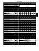
SAP ORDERING NO. PG95SAS24026A PG95SAS30040A PG95SAS42060B PG95SAS48080B PG95SAS60080C PG95SAS42100C PG95SAS60100C PG95SAS60120D PG95SAS60140D RATED CASING HEATING DIMENSIONS (IN.) OUTPUT† AFUE ENERGY STARR H D W (BTUH) UPFLOW/ HORIZONTAL DOWNFLOW 35 35 35 35 35 35 35 35 35 29.5 29.5 29.5 29.5 29.5 29.5 29.5 29.5 29.5 14.2 14.2 17.5 17.5 21.0 21.0 21.0 24.5 24.5 25,000 39,000 58,000 78,000 78,000 97,000 97,000 117,000 135,000 95.5% 95.5% 95.5% 95.5% 95.5% 95.5% 95.5% 95.5% 95.5% 95.0% 95.
SPECIFICATIONS Heating Capacity and Efficiency High Input (BTUH) Heat High Output (BTUH) Heat Certified Temperature High Heat Rise Range ºF (ºC) 24026 30040 42060 48080 60080 42100 60100 60120 60140 26,000 40,000 60,000 80,000 80,000 100,000 100,000 120,000 140,000 25,000 39,000 58,000 78,000 78,000 97,000 97,000 117,000 135,000 40 - 70 (22 - 39) 45 - 75 (25 - 42) 60120 0.20 0.5 2245 2105 5 6 60140 0.20 0.5 2175 2035 5 6 1 14.1 1 14.
MODEL NUMBER NOMENCLATURE Example of a Model Number 1 Brand P 2 Product G 3-4 Base Effy. 96 5 Voltage/Motor V 6 Major Series A 8-9 10 - 12 Cooling Cap. Heating Cap. 30 040 7 Htg. Stages T 13 Width/Variation A 14 Minor Series A A - 14.2” Std. B - 17.5” Std. C - 21.0” Std. D - 24.5” Std.
ACCESSORIES PART NUMBER 24026 30040 42060 48080 60080 42100 60100 60120 60140 KGADC0101BVC KGAVT0701CVT KGAVT0801CVT KGAVT0101BRA KGAVT0201BRA KGAAC0101RVC D D D D D D D D D KGAHT0201CFP KGAAD0110PVC KGACK0101HCK P908 ---0001 KGAET0201ETK D D D D D D D D D D D D D D D D D D D D D D D D KGASB0201ALL KGADA0101ALL KGADA0201ALL KGADA0301ALL KGARP0301B14 KGARP0301B17 KGARP0301B21 KGARP0301B24 D D D D D D D D D D D D D D D D D D D D D D D D D D D D D D See Venting Tables
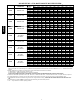
AIR DELIVERY - CFM (BOTTOM RETURN WITH FILTER) PG95SAS UNIT SIZE RETURN-AIR CONNECTION 024026 SIDE/BOTTOM 030040 SIDE/BOTTOM 042060 SIDE/BOTTOM 048080 SIDE/BOTTOM 060080 BOTTOM or TWO-SIDES 3,4 042100 SIDE/BOTTOM 060100 BOTTOM or TWO-SIDES 3,4 060120 BOTTOM or TWO-SIDES 3,4 060140 BOTTOM or TWO-SIDES 3,4 SPEED TAPS 2 Black Yellow Blue Red 5 Black Yellow Blue Red Black Yellow Orange Blue Red 5 Black Yellow Orange Blue Red 5 Black Yellow Orange Blue Red Black Blue Yellow 5 Red 5 Black Ye
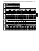
MAXIMUM ALLOWABLE EXPOSED VENT LENGTHS IN UNCONDITIONED SPACE - FT. Winter Design Temp °F Pipe Dia. In. 20 0 -20 -40 Unit Size Winter Design Temp °F Pipe Dia. in. 20 0 -20 -40 Pipe Dia. in. 20 0 -20 -40 2 1½ 2 1½ 2 20 5 20 5 50 25 15 10 45 20 10 5 60 30 20 15 50 25 15 10 40,000* BTUH Uninsulated Pipe Dia. in. 20 0 -20 -40 Unit Size Winter Design Temp °F Pipe Dia. in. 20 0 -20 -40 3/8-in. Insulation 60,000 BTUH 3/8-in. Insulation Uninsulated 1/2-in. Insulation 1/2-in.
MAXIMUM ALLOWABLE EXPOSED VENT LENGTHS IN UNCONDITIONED SPACE METERS Unit Size Winter Design Temp °C Pipe Dia. mm -7 -18 -29 -40 Unit Size PG95SAS Winter Design Temp °C Pipe Dia. mm -7 -18 -29 -40 Pipe Dia. mm -7 -18 -29 -40 51 38 51 38 51 6.1 1.5 6.1 1.5 15.2 7.6 4.6 3.0 13.7 6.1 3.0 1.5 18.3 9.1 6.1 4.6 15.2 7.6 4.6 3.0 40,000* BTUH Uninsulated Pipe Dia. mm -7 -18 -29 -40 Unit Size Winter Design Temp °C Pipe Dia. mm -7 -18 -29 -40 3/8-in. Insulation 1/2-in.
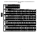
MAXIMUM EQUIVALENT VENT LENGTHS Table 1 – Maximum Equivalent Vent Length -- Ft. NOTE: Maximum Equivalent Vent Length (MEVL) includes standard and concentric vent termination and does NOT include elbows. Use Table 2 - Deductions from Maximum Equivalent Vent Length to determine allowable vent length for each application. Unit Size Pipe Dia.
Venting System Length Calculations The Total Equivalent Vent Length (TEVL) for EACH combustion air or vent pipe equals the length of the venting system, plus the equivalent length of elbows used in the venting system from Table 2. Standard vent terminations or factory accessory concentric vent terminations count for zero deduction. See vent system manufacturer’s data for equivalent lengths of flexible vent pipe or other termination systems.
RETURN AIR TEMPERATURE This furnace is designed for continuous return--air minimum temperature of 60_F (15_C) db or intermittent operation down to 55_F (13_C) db such as when used with a night setback thermometer. Return--air temperature must not exceed 80_F (27_C) db. Failure to follow these return air limits may affect reliability of heat exchangers, motors and controls.
DOWNFLOW SUBBASE LOCATING TAB 1 1/4-IN. TYP PLENUM OPENING B A D 1 2 3 4 LOCATING TAB C FACTORY-SUPPLIED FIELD-INSTALLED INSULATION 4 PG95SAS A97427 3 2 1 A88207 Assembled Disassembled DIMENSIONS (IN. / MM) PLENUM OPENING* FLOOR OPENING HOLE NO.
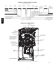
TYPICAL WIRING SCHEMATIC FIELD 24-VOLT WIRING FIELD 115-, 208/230-, 460-VOLT WIRING FACTORY 24-VOLT WIRING FACTORY 115-VOLT WIRING NOTE 2 W FIVE WIRE Y R G 1-STAGE THERMOSTAT TERMINALS FIELD-SUPPLIED FUSED DISCONNECT THREE-WIRE HEATINGONLY BLK BLK WHT WHT GND 115-VOLT FIELD- JUNCTION SUPPLIED BOX FUSED DISCONNECT C O N T R O L 208/230- OR 460-VOLT THREE PHASE W2 COM W/W1 Y/Y2 NOTE 1 R GND CONDENSING UNIT G 24-VOLT TERMINAL BLOCK FURNACE 208/230VOLT SINGLE PHASE PG95SAS BLOWER DOOR SW
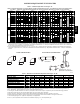
PG95SAS FURNACE SIZE 24026 30040 42060 48080 60080 42100 60100 60120 60140 25 1/8 [638.7] 14 A CABINET WIDTH B OUTLET WIDTH C BOTTOM INLET WIDTH D AIR INTAKE 14--- 3/16 (361) 12--- 1/2 (319) 12--- 9/16 (322) 7--- 1/8 (181) 17--- 1/2 (445) 15--- 7/8 (403) 16 (406) 8--- 3/4 (222) 21 (533) 19--- 3/8 (492) 19--- 1/2 (495) 10--- 1/2 (267) 24--- 1/2 (622) 22--- 7/8 (581) 23 (584) 12--- 1/4 (311) 21 [534.0] 26 5/16 [668.8] 22 [558.3] (BOTH SIDES) 1 (BOTH SIDES) [25.4] 7/8 [22.
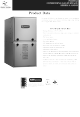
GUIDE SPECIFICATIONS System Description Furnish a ______________________ 4--way multipoise gas--fired condensing furnace for use with natural gas or propane (factory-authorized conversion kit required for propane). Quality Assurance Unit will be designed, tested and constructed to the current ANSI Z 21.47/CSA 2.3 design standard for gas--fired central furnaces. Unit will be third party certified by CSA to the current ANSI Z 21.47/CSA 2.3 design standard for gas--fired central furnaces.