
Specs

3
SPECIFICATIONS
The furnace should be sized to provide 100 percent of the design
heating load requirement plus any margin that occurs because of
furnace model size capacity increments. None of the furnace
model sizes can be used if the heating load is 12,000 BTUH or
lower. Use Air Conditioning Contractors of America (Manual J
and S); American Society of Heating, Refrigerating, and
Air-Conditioning Engineers; or other approved engineering
method to calculate heating load estimates and select the furnace.
Excessive oversizing of the furnace may cause the furnace and/or
vent to fail prematurely , customer discomfort and/or vent freezing.
Failure to follow these guidelines is considered faulty installation
and/or misapplication of the furnace; and resulting failure, damage,
or repairs may impact warranty coverage.
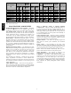
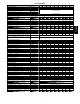
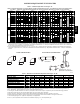
Heating Capacity and Efficiency 24026 30040 42060 48080 60080 42100 60100 60120 60140
Input
High
Heat
(BTUH) 26,000 40,000 60,000 80,000 80,000 100,000 100,000 120,000 140,000
Output
High
Heat
(BTUH) 25,000 39,000 58,000 78,000 78,000 97,000 97,000 117,000 135,000
Certified Temperature
Rise Range ºF (ºC)
High Heat
25 - 55
(14 - 31)
40 - 70
(22 - 39)
40 - 70
(22 - 39)
40 - 70
(22 - 39)
40 - 70
(22 - 39)
40 - 70
(22 - 39)
40 - 70
(22 - 39)
40 - 70
(22 - 39)
45 - 75
(25 - 42)
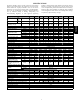
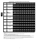
Airflow Capacity and Blower Data 24026 30040 42060 48080 60080 42100 60100 60120 60140
Rated External Static
Pressure (in. W.C.)
Heating 0.10 0.10 0.12 0.15 0.15 0.20 0.20 0.20 0.20
Cooling 0.5 0.5 0.5 0.5 0.5 0.5 0.5 0.5 0.5
Airflow Delivery
@ Rated ESP (CFM)
High Heat 675 820 980 1040 1695 1510 1680 2245 2175
Cooling 775 905 1420 1600 1970 1545 2065 2105 2035
Cooling Capacity (tons)
400 CFM/ton 1.5 2 3.5 4 5 4 5 5 5
350 CFM/ton 2 2.5 4 4.5 5.5 4.5 6 6 6
Direct-Drive Motor Type Permanent Split Capacitor (PSC)
Direct-Drive Motor HP 0.25 0.5 0.5 0.75 1 0.5 1 1 1
Motor Full Load Amps 2.8 6.2 6.8 7.9 13.8 6.5 13.8 14.1 14.1
RPM Range 500 -1150
Speed Selections 4 4 5 5 5 4 5 5 5
Blower Wheel Dia x Width in. 11 x 7 11 x 7 11 x 8 11 x 8 11 x 10 11 x 10 11 x 10 11 x 11 11 x 11
Air Filtration System Field Supplied
Filter Used for Certified Watt Data* KGAWF**06UFR
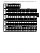
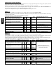
Electrical Data 24026 30040 42060 48080 60080 42100 60100 60120 60140
Input Voltage Volts-Hertz-Phase 115-60-1
Operating Voltage Range Min-Max 104-127
Maximum Input Amps Amps 3.6 6.8 8.4 9.6 14.5 7.6 14.6 14.9 14.9
Unit Ampacity Amps 5.4 9.5 11.5 13.0 19.1 10.4 19.2 19.6 19.6
Minimum Wire Size AWG 14 14 14 14 12 14 12 12 12
Maximum Wire Length
@ Minimum Wire Size
Feet 68 39 32 28 30 35 29 29 29
(M) (20.7) (11.9) (9.8) (8.5) (9.1) (10.7) (8.8) (8.8) (8.8)
Maximum Fuse/Ckt Bkr
(Time-Delay Type Recom-
mended)
Amps 15 15 15 15 20 15 20 20 20
Transformer Capacity (24vac output) 40 VA
External Control Power
Available
Heating 27.9 VA
Cooling 34.6 VA
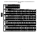
Controls 24026 30040 42060 48080 60080 42100 60100 60120 60140
Gas Connection Size 1/2" - NPT
Burners (Monoport) 2 2 3 4 4 5 5 6 7
Gas Valve (Redundant) Manufacturer White Rogers
Minimum Inlet Gas pressure (in. W.C.) 4.5
Maximum Inlet Gas pressure (in. W.C.) 13.6
Ignition Device Silicon Nitride
Limit Control 220 165 180 170 200 180 180 160 155
Heating Blower Control (Heating Off-Delay) Adjustable: 90, 120, 150, 180 seconds
Cooling Blower Control (Time Delay Relay) 90 seconds
Communication System none
Thermostat Connections Com24V,R,W,G,Y
Accessory Connections EAC (115vac); HUM (24vac)
PG95SAS