Required Notice for Massachusetts Installations PG95SAS IMPORTANT The Commonwealth of Massachusetts requires compliance with regulation 248 CMR as follows: 5.08: Modifications to NFPA--54, Chapter 10 2) Revise 10.8.3 by adding the following additional requirements: a.
SAFETY CONSIDERATIONS ! WARNING CUT HAZARD Failure to follow this caution may result in personal injury. FIRE, EXPLOSION, ELECTRICAL SHOCK, AND CARBON MONOXIDE POISONING HAZARD Sheet metal parts may have sharp edges or burrs. Use care and wear appropriate protective clothing, safety glasses and gloves when handling parts, and servicing furnaces. Failure to follow this warning could result in dangerous operation, personal injury, death, or property damage.
13. These furnaces SHALL NOT be installed directly on carpeting, combustible tile, or any other combustible material other than wood flooring. In downflow installations, factory accessory floor base MUST be used when installed on combustible materials and wood flooring. Special base is not required when this furnace is installed on manufacturer’s Coil Assembly Part No. CNRV, CNPV, CAP, or CAR or when Coil Box Part No. KCAKC is used. See Table 2 for clearance to combustible construction information.
Gas furnaces manufactured on or after May 1, 2017 are not permitted to be used in Canada for heating of buildings or structures under construction. Electrical Connections S US: Current edition of National Electrical Code (NEC) NFPA 70 S CANADA: Canadian Electrical Code CSA C22.1 Condensate Drain Connection S US: Current edition of National Standard Plumbing Code , Section 8.7. S Canada: Current edition of National Plumbing Code of Canada in Canada.
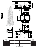
A12267 PG95SAS FURNACE SIZE 24026 30040 42060 48080 60080 42100 60100 60120 60140 A CABINET WIDTH B OUTLET WIDTH C BOTTOM INLET WIDTH D AIR INTAKE 14--- 3/16 (361) 12--- 1/2 (319) 12--- 9/16 (322) 7--- 1/8 (181) 17--- 1/2 (445) 15--- 7/8 (403) 16 (406) 8--- 3/4 (222) 21 (533) 19--- 3/8 (492) 19--- 1/2 (495) 10--- 1/2 (267) 24--- 1/2 (622) 22--- 7/8 (581) 23 (584) 12--- 1/4 (311) Fig. 1 -- Dimensional Drawing 6 SHIP WT. LB (KG) 118.0 (53.5) 123.0 (55.4) 144.0 (64.8) 154.0 (69.3) 161.
THE BLOWER IS LOCATED BELOW THE BURNER SECTION, AND CONDITIONED AIR IS DISCHARGED UPWARD. THE BLOWER IS LOCATED TO THE LEFT OF THE BURNER SECTION, AND CONDITIONED AIR IS DISCHARGED TO THE RIGHT. THE BLOWER IS LOCATED ABOVE THE BURNER SECTION, AND CONDITIONED AIR IS DISCHARGED DOWNWARD A12181 Fig. 2 -- Multipoise Orientations 80 / 27˚C 60 / 16˚C SUPPLY AIR SEE PRODUCT DATA FOR ACCESSORY CONDENSATE TRAP HEATER AND CONDENSATE DRAIN LINE PROTECTION. A150573 Fig.
LOCATION ! ! CAUTION CARBON MONOXIDE POISONING / COMPONENT DAMAGE HAZARD PERSONAL INJURY AND/OR PROPERTY DAMAGE HAZARD Failure to follow this warning could result in personal injury or death and unit component damage. Improper use or installation of this furnace may result in premature furnace component failure.
WARNING ! CAUTION FIRE HAZARD FURNACE CORROSION HAZARD Failure to follow this warning could result in personal injury, death and/or property damage. Failure to follow this caution may result in furnace damage. Air for combustion must not be contaminated by halogen compounds, which include fluoride, chloride, bromide, and iodide. These elements can corrode heat exchangers and shorten furnace life.
The opening shall commence within 12 in. (300 mm) of the ceiling. Appliances in the space shall have clearances of at least 1 in. (25 mm) from the sides and back and 6 in. (150 mm) from the front. The opening shall directly communicate with the outdoors or shall communicate through a vertical or horizontal duct to the outdoors or spaces (crawl or attic) that freely communicate with the outdoors.
Table 3 – Minimum Free Area Required for Each Combustion Air Opening or Duct to Outdoors TWO HORIZONTAL DUCTS (1 SQ. IN./2,000 BTUH) (1,100 SQ. MM/KW) FURNACE INPUT (BTUH) Free Area of Opening and Duct Sq. In (Sq. mm) 13 (8388) 20 (12904) 30 (19355) 40 (25807) 50 (32258) 60 (38709) 70 (45161) 26,000* 40,000* 60,000 80,000 100,000 120,000 140,000* SINGLE DUCT OR OPENING (1 SQ. IN./3,000 BTUH) (734 SQ. MM/KW) Free Area of Opening and Duct Sq. In (Sq.
CONDENSATE TRAP NOTICE Condensate Trap -- Upflow Orientation When the furnace is installed in the upflow position, it is not necessary to relocate the condensate trap or associated tubing. Refer to Fig. 8 for upflow condensate trap information. Refer to Condensate Drain section for information how to install the condensate drain. The field--supplied, accessory horizontal drain trap grommet is ONLY REQUIRED FOR DIRECT VENT APPLICATIONS.
Remove pressure switch tube from front pressure switch and discard. A new tube is shipped in the loose parts bag. Remove relief tube from relief port on condensate trap. Remove tube from relief port. Loosen clamp on inlet to vent elbow. PG95SAS Remove the screw that secures the trap to the collector box and remove trap. Remove middle and bottom plugs. DO NOT DISCARD.
PG95SAS Remove plug from collector box. DO NOT DISCARD. If alternate vent position is required, loosen clamp on inlet of vent elbow. Remove the screw that secures the trap to the collector box and remove trap. Unconverted Factory Configuration As Viewed in the Horizontal Right Orientation NOTE: Remove knockout in casing before reïinstalling the condensate trap. Slide relief tube in standïoffs to adjust length. Vent elbow shown in alternate orientation. Tighten clamp on inlet to vent elbow 15 lb.ïin.
5 Remove the screw that secures the condensate trap to the collector box and remove trap. If alternate vent position is required, loosen clamp on vent elbow inlet. Remove relief tube from relief port on condensate trap. PG95SAS Remove front pressure switch tube and discard. A new tube is shipped in the Loose Parts bag. Remove relief tube from port on collector box. Remove middle and right plug from collector box. DO NOT DISCARD.
CONDENSATE DRAIN CONNECTION ! CAUTION FROZEN AND BURST WATER PIPE HAZARD Failure to protect against the risk of freezing may result in property damage. PG95SAS Special precautions MUST be made if installing furnace in an area which may drop below freezing. This can cause improper operation or damage to equipment. If furnace environment has the potential of freezing, the drain trap and drain line must be protected.
2. To allow for servicing the trap, the condensate drain elbow in the loose parts bag can be used to make a coupler to allow for future service of the condensate trap and drain line. 3. Remove the knock-out for the condensate trap in the side of the casing. 4. Install the drain trap grommet in the casing if required for direct--vent applications. If necessary, remove the trap, install the grommet and re-install the trap. 5.
Evaporator Coil + ++ + DIRECTION OF AIRFLOW + Condensing Furnace + + + + + - - - PG95SAS Furnace condensate does not flow consistently when drain is at positive pressure. + + Evaporator Coil + Open standpipe + 3/4” PVC + 3/4 + + + Condensing Furnace 3/4 + + + DIRECTION OF AIRFLOW DIRECTION OF AIRFLOW Positive pressure extends into coil condensate drain (no trap). + Evaporator Coil + <+ + Blower + Blower creates positive pressure.
Open standpipe for coil or humidifier drain Evaporator Coil + ++ Air gap here 3/4” PVC DIRECTION OF AIRFLOW + TEE bag.) (1/2” CPVC to 3/4” PVC adapter from loose parts 3/4 + + 3/4” PVC Condensing Furnace + 3/4 + + + + Open standpipe Air gap required when another drain is connected to furnace drain. 3/4 + TEE (1/2” CPVC to 3/4” PVC adapter from loose parts bag.
INSTALL CLAMPS ON DRAIN TUBE ATTACH DRAIN TUBE TO CONDENSATE DRAIN TRAP Attach elbow to condensate trap PULL DRAIN STUB THROUGH CASING Formed end of grommet Cut formed end off condensate drain elbow s Connect short end of “Z” pipe to modified drain elbow Factory supplied 1/2ïin. CPVC to 3/4ïin. PVC adapter PG95SAS TRAP, DRAIN ELBOW WITH DISCHARGE PIPE Formed end of grommet Open spring clamp. Insert 1/2ïin. to 3/4ïin. CPVC to PVC adapter or 1/2ïin.
! WARNING FIRE HAZARD A failure to follow this warning could cause personal injury, death and/or property damage. Never connect return--air ducts to the back of the furnace. Follow instructions below. The return--air duct must be connected to bottom, sides (left or right), or a combination of bottom and side(s) of main furnace casing. Bypass humidifier may be attached into unused return air side of the furnace casing. See Fig. 26, 27, and 28.
WARNING ! FIRE, EXPLOSION, AND CARBON MONOXIDE POISONING HAZARD Failure to follow this warning could result in personal injury, death, or property damage. Do not install the furnace on its back or hang furnace with control compartment facing downward. Safety control operation will be adversely affected. Never connect return--air ducts to the back of the furnace. ! CAUTION PG95SAS MINOR PROPERTY HAZARD Failure to follow this caution may result in minor property damage.
Design the filter and associated ductwork for the best match of pressure drop versus filter size. Best practice usually chooses filter systems with pressure drops under 0.2 in. W.C. (50 Pa), with the best blower electrical efficiency and system airflow performance occurring with filter pressure drops under 0.1 in. W.C. (25 Pa). Due to the relatively high pressure drops of 1--in. (25 mm) thick after--market filter media, it is recommended that the filtration system be designed for at least 2--in.
Table 6 – Filter Media Pressure Drop (Clean) Versus Face Velocity-- In. W.C. (Pa) FPM 200 300 400 500 600 700 Representative After-Market Filter Media* Fiberglass* Pleated* (1-in. / 2.5 cm) (2-in. / 5 cm) (1-in. / 2.5 cm) (2-in. / 5 cm) 0.05 (13) 0.08 (20) 0.18 (47) 0.12 (31) 0.09 (22) 0.13 (34) 0.30 (75) 0.21 (52) 0.13 (32) 0.20 (50) 0.31 (78) 0.18 (44) 0.27 (69) 0.23 0.29 - Factory-Accessory Washable (1-in. / 2.5 cm) 0.04 (10) 0.05 (14) 0.07 (17) 0.08 (21) 0.09 (23) 0.
FURNACE (OR COIL CASING WHEN USED) FURNACE APPROVED COIL ASSEMBLY OR COIL BOX COMBUSTIBLE FLOORING COMBUSTIBLE FLOORING A PLENUM OPENING D DOWNFLOW SUBBASE FLOOR OPENING SHEET METAL PLENUM SHEET METAL PLENUM FLOOR OPENING C FLOOR OPENING A10491 Fig. 21 -- Installation on Combustible Flooring Table 8 – Opening Dimensions -- In. (mm) FURNACE CASING WIDTH IN.
UPFLOW PERFORATED DISCHARGE DUCT FLANGE DOWNFLOW HORIZONTAL 90° 90° YES YES YES 120° MIN YES 120° MIN YES 120° MIN NO NO PG95SAS YES NO A10493 Fig. 22 -- Duct Flanges 5/ 16 (8mm) (8mm) 5/ 16 1 3/4 (44mm) 1 3/4 (44mm) (8mm) 5/16 BOTTOM CLOSURE PANEL (8mm) 5/ 16 (44mm) 1 3/ 4 3/ (44mm) 1 4 BOTTOM PLATE A89014 A11092 Fig. 23 -- Leveling Legs Fig. 24 -- Removing Bottom Closure Panel LEVEL 0-IN. (0 MM) TO 1/2-IN. (13 MM) MAX MIN 1/4-IN. (6 MM) TO 1/2-IN.
A11036 A11037 Fig. 26 -- Upflow Return Air Configurations and Restrictions Fig. 27 -- Downflow Return Air Configurations and Restrictions HORIZONTAL TOP RETURN NOT PERMITTED FOR ANY MODEL A11038 Fig. 28 -- Horizontal Return Air Configurations and Restrictions 27 PG95SAS ANY COMBINATION OF 1, 2, OR 3 PERMITTED.
COMBUSTION - AIR PIPE (SEE VENTING SECTION) 30 IN. (762 mm) MIN. WORK AREA PG95SAS 2-IN. (51 mm) ROLLOUT PROTECTION REQUIRED Install 12” x 22” (305x559 mm) sheet metal in front of burner compartment area. The sheet metal MUST extend underneath the furnace casing by 1-in. (25 mm) with the door removed. The bottom closure panel may be used for flame roll-out protection when bottom of furnace is used for return air connection. A150580 Fig.
AIR DUCTS NOTICE Many states, provinces and localities are considering or have implemented standards and/or restrictions on duct sizing practices, ductwork leakage, and/or ductwork thermal, airflow and electrical efficiencies. CONSULT LOCAL CODE OFFICIALS for ductwork design and performance requirements in your area.
PG95SAS Table 9 – Air Delivery -- CFM (With Filter) UNIT SIZE RETURN-AIR CONNECTION 024026 SIDE/BOTTOM 030040 SIDE/BOTTOM 042060 SIDE/BOTTOM 048080 SIDE/BOTTOM 060080 BOTTOM or TWO-SIDES 3,4 042100 SIDE/BOTTOM 060100 BOTTOM or TWO-SIDES 3,4 060120 BOTTOM or TWO-SIDES 3,4 060140 BOTTOM or TWO-SIDES 3,4 SPEED TAPS 2 Black Yellow Blue Red 5 Black Yellow Blue Red Black Yellow Orange Blue Red 5 Black Yellow Orange Blue Red 5 Black Yellow Orange Blue Red Black Blue Yellow 5 Red 5 Black Yellow
GAS PIPING WARNING FIRE OR EXPLOSION HAZARD A failure to follow this warning could result in personal injury, death, and/or property damage. FIRE OR EXPLOSION HAZARD Failure to follow this warning could result in personal injury, death, and/or property damage. If local codes allow the use of a flexible gas appliance connector, always use a new listed connector. Do not use a connector which has previously served another gas appliance.
ELECTRICAL CONNECTIONS Table 10 – Maximum Capacity of Pipe NOMINAL IRON PIPE SIZE IN. (MM) 1/2 (13) 3/4 (19) 1 ( 25) 1-1/4 (32) 1-1/2 (39) LENGTH OF PIPE --- FT (M) 10 (3.0) 20 (6.0) 30 (9.1) 40 (12.1) 50 (15.2) 175 360 680 1400 2100 120 250 465 950 1460 97 200 375 770 1180 82 170 320 660 990 73 151 285 580 900 ! ELECTRICAL SHOCK, FIRE OR EXPLOSION HAZARD Failure to follow safety warnings could result in dangerous operation, serious injury, death or property damage.
Electrical Box on Furnace Casing Side Furnace must have a 115-v power supply properly connected and grounded. NOTE: Proper polarity must be maintained for 115-v wiring. If polarity is incorrect, control LED status indicator light will flash rapidly and furnace will NOT operate. Verify that the voltage, frequency, and phase correspond to that specified on unit rating plate. Also, check to be sure that service provided by utility is sufficient to handle load imposed by this equipment.
6. Attach furnace J--Box cover to mounting bracket with screws supplied in loose parts bag. Do not pinch wires between cover and bracket. ! WARNING FIRE, EXPLOSION, ELECTRICAL SHOCK, AND CARBON MONOXIDE POISONING HAZARD Failure to follow this warning could result in dangerous operation, personal injury, death, or property damage. Do not drill into blower shelf of furnace to route control wiring. Route any control or accessory wiring to the blower compartment through external knockouts on the casing.
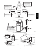
GROUND NEUTRAL PG95SAS LINE VOLTAGE ELECTRIC DISCONNECT SWITCH COPPER WIRE ONLY ALUMINUM WIRE A11146 A12226 Fig. 34 -- Field--Supplied Electrical Box on Furnace Casing Fig. 33 -- Installing J--Box (When Used) To HUM Terminal On To Humidifier Leads Furnace Control Board 24 V Coil To Humidifier Leads To Com/24V Screw Terminal on Thermostat Strip A11157 Fig.
FIELD 24-V WIRING FIELD 115-, 208/230-, 460-V WIRING FACTORY 24-V WIRING FACTORY 115-V WIRING NOTE 2 W FIVE WIRE THREE-WIRE HEATING-ONLY C R G Y THERMOSTAT TERMINALS FIELD-SUPPLIED DISCONNECT 208/230- OR 460-V THREE PHASE BLOWER DOOR SWITCH BLK W BLK WHT C O N T R O L WHT GND GND 115-V FIELDSUPPLIED DISCONNECT AUXILIARY J-BOX R 208/230-V SINGLE PHASE G COM GND NOTE 1 CONDENSING UNIT Y TWO WIRE PG95SAS 24-V TERMINAL BLOCK FURNACE NOTES: 1.
VENTING Special Venting Requirements for Installations in Canada Consignes spéciales pour l’installation de ventilation au Canada Installation in Canada must conform to the requirements of CSA B149 code. Vent systems must be composed of pipe, fittings, cements, and primers listed to ULC S636.
! WARNING CARBON MONOXIDE POISONING HAZARD PG95SAS Failure to follow the steps outlined below for each appliance connected to the venting system being placed into operation could result in carbon monoxide poisoning or death. The following steps shall be followed for each appliance connected to the venting system being placed into operation, while all other appliances connected to the venting system are not in operation: 1. Seal any unused openings in venting system. 2.
Table 12 – Vent Termination Kit for Direct Vent (2--pipe) Systems Approved Two- Pipe Termination Fittings 2--in. 2 1/2--in. 3--in. (51 mm) (64 mm) (76--mm) Yes No No Yes No No Vent and Combustion Air Pipe Diameters 1 1/2--in. (38 mm) 2--in. (51 mm) 1 1/2--in. (38 mm) No No 2 1/2--in. (64 mm) No No No Yes No 3--in. (76--mm) 4--in. (102 mm) No No No No No No Yes Yes No Yes Direct Vent / 2-Pipe System 4--in. (102 mm) No No Allowable Concentric Vent Kit 2--in. (51 mm) 2--in. (51 mm) 2--in.
combustion air system is less susceptible to damage or contamination. The termination is usually located away from adjacent structures or other obstacles such as inside corners, windows, doors or other appliances. It is less prone to icing conditions, and it often has less visible vent vapors.
OPTIONAL CONFIGURATION FOR COMBUSTION AIR INLET PIPE In applications where there is a risk of excessive moisture entering the combustion air inlet pipe, a moisture trap may be added to the inlet pipe to help prevent moisture from entering the furnace from the combustion air inlet pipe. See Fig. 56. When sizing venting systems, the equivalent length of the optional moisture trap (15 feet/5 M) must be taken into account.
PG95SAS The vent pipe may pass through unconditioned areas. The amount of exposed pipe allowed is shown in Table 15. 1. Using winter design temperature (used in load calculations), find appropriate temperature for your application and furnace model. 2. Determine the amount of total and exposed vent pipe. 3. Determine required insulation thickness for exposed pipe length(s). 4.
3. Chamfer outside edge of pipe for better distribution of primer and cement. 4. Clean and dry all surfaces to be joined. 5. Check dry fit of pipe and mark insertion depth on pipe. 6. Insert the vent pipe into the vent elbow. 7. Torque clamp on vent elbow 15 lb--in. 8. Torque clamp on vent coupling 15 lb--in. 9. Insert the combustion air pipe into the adapter. 10. Pilot drill a screw hole through the adapter into the combustion air pipe and secure the pipe to the adapter with sheet metal screws.
PG95SAS Optional Installation of the Vent Pipe NOTE: DO NOT USE THIS TECHNIQUE FOR POLYPROPYLENE VENTING SYSTEMS. This option provides a disconnect point for the vent pipe. The vent pipe must be cemented to the plastic vent pipe adapter to maintain a sealed vestibule. See Fig. 47. 1. Insert a length of vent pipe through the casing into the outlet of the vent elbow. 2. Slide the plastic vent pipe adapter over the length of the vent pipe down to the furnace casing.
termination, or pair of vent terminations, must be at least 36 in. (914 mm) away from the first two terminations. It is important that vent terminations be made as shown in Fig. 51 to avoid recirculation of vent gases. NOTICE RECOMMENDED SUPPORT FOR VENT TERMINATIONS Inducer Outlet Restrictor Determine an appropriate location for termination kit using the guidelines provided in section “Locating The Vent Termination” in this instruction. 1.
Table 15 – Maximum Allowable Exposed Vent Lengths in Unconditioned Space -- Ft. Unit Size Winter Design Temp °F Pipe Dia. In. 20 0 -20 -40 26,000* BTUH 3/8" Insulation 1½ 2 0" Insulation 1½ 2 20 5 20 5 50 25 15 10 Unit Size Winter Design Temp °F Pipe Dia. in. 20 0 -20 -40 1/2" Insulation 1½ 2 45 20 10 5 60 30 20 15 50 25 15 10 40,000* BTUH Uninsulated 1½ 2 2½ 20 10 5 20 5 20 5 3/8-in. Insulation 1/2-in.
Maximum Allowable Exposed Vent Length in Unconditioned Space (Metric) Winter Design Temp °C Pipe Dia. mm -7 -18 -29 -40 0" Insulation 38 51 6.1 1.5 6.1 1.5 15.2 7.6 4.6 3.0 Unit Size Winter Design Temp °C Pipe Dia. mm -7 -18 -29 -40 26,000* BTUH 3/8" Insulation 38 51 1/2" Insulation 38 51 13.7 6.1 3.0 1.5 18.3 9.1 6.1 4.6 15.2 7.6 4.6 3.0 40,000* BTUH Uninsulated 38 51 64 6.1 3.0 1.5 6.1 1.5 6.1 1.5 3/8-in. Insulation 1/2-in. Insulation 38 38 51 6.1 6.1 6.1 4.6 64 15.2 13.7 7.6 6.
Table 16 – Maximum Equivalent Vent Length -- Ft. NOTE: Maximum Equivalent Vent Length (MEVL) includes standard and concentric vent termination and does NOT include elbows. Use Table 17 - Deductions from Maximum Equivalent Vent Length to determine allowable vent length for each application. PG95SAS Unit Size Pipe Dia. (in) 0--- 2000 2001--- 3000 3001--- 4000 4001--- 4500 Altitude 4501--- 5000 (feet) 5001--- 6000 6001--- 7000 7001--- 8000 8001--- 9000 9001--- 1000 0 Unit Size Pipe Dia.
Venting System Length Calculations The Total Equivalent Vent Length (TEVL) for EACH combustion air or vent pipe equals the length of the venting system, plus the equivalent length of elbows used in the venting system from Table 17. Standard vent terminations or factory accessory concentric vent terminations count for zero deduction. See vent system manufacturer’s data for equivalent lengths of flexible vent pipe or other termination systems.
Attach gaskets to vent pipe and combustion air adapters. Vent Coupling and Adapter A13074 PG95SAS Fig. 38 -- Vent Coupling and Adapter with Gaskets TABS ON THE INDUCER OUTLET RESTRICTOR SNAP INTO THE SLOTS AT THE OUTLET OF THE INDUCER FOR USAGE: SEE MAXIMUM EQUIVALENT VENT LENGTH TABLE (10FT. (3.1 M) OF VENT OR LESS ONLY) A170006 Fig. 39 -- Inducer Vent Elbow Slope vent pipe back to the furnace at least ¼” per foot Avoid short horizontal offsets with 90 deg. Elbows.
FURNACE NOT IN HORIZONTAL SECTION PIPE DIAMETER TRANSITION IN VERTICAL SECTION A93034 PG95SAS Fig. 41 -- Combustion Air and Vent Pipe Diameter Transition Location and Elbow Configuration Clearance distances for items greater than 3 feet (1 meter ) away from the inside corner, refer to the Inside Corner Clearance Table. No operable windows, doors or intakes of any type within the shaded areas of Wall A and B. For all other items, refer to the Inside Corner Clearance Table. 3 ft. (1 M) 3 ft.
Inside Corner Terminations PG95SAS Inside corner vent terminations are permitted provided that: S Only two exterior walls come together to form an angle of 90 degrees to 135 degrees. There are no other exterior walls attached to either wall to form an alcove. S The clearance distances apply when the vent is at least 3 feet (1 meter) from, but not more than 6 feet (2 meters) away from an inside corner.
7 Rotate vent elbow to required position. 3 6 2 5 4 5 1 Any other unused knockout may be used for combustion air connection. 4 Rotate vent elbow to required position. 5 1 3 2 & 5 6 UPFLOW LEFT CONFIGURATION DOWNFLOW LEFT CONFIGURATION A11309A A11311A Rotate vent elbow to required position. 4 5 1 2 5 3 7 6 2 5 1 Any other unused knockout may be used for combustion air connection. Any other unused knockout may be used for combustion air connection.
PG95SAS ALTERNATE COMBUSTION AIR CONNECTIONS HORIZONTAL LEFT ---VERTICAL VENT CONFIGURATION HORIZONTAL RIGHT ---VERTICAL VENT CONFIGURATION A11327A A11337 Alternate combustion air connection. 4 Rotate vent elbow to required position.
NOTES FOR VENTING OPTIONS Attach vent pipe adapter with gasket to furnace casing. Align notches in rubber coupling over standoffs on adapter. Slide clamps over the coupling. Slide vent pipe through adapter and coupling into vent elbow. Insert vent pipe into vent elbow. Torque all clamps 15 lb.--in. Attach combustion air pipe adapter with gasket to furnace. Attach combustion air pipe to adapter with silicone. Pilot drill a1/8--in. hole in adapter and secure with a #7 x 1/2--in. sheet metal screw.
V PG95SAS V A12326 NOTE: The following is based upon National codes for gas appliances and is provided as a reference. Refer to local codes which may supersede these standards and/or recommendations.
V A12325 NOTE: The following is based upon National codes for gas appliances and is provided as a reference. Refer to local codes which may supersede these standards and/or recommendations.
¾ in. (222mm) for 3 in. (76mm) PG95SAS ¾ in. (172mm) for 2 in. (51mm) 12 in. (305mm) min. separation between bottom of combustion air and bottom of vent (Typ.) A13305 Fig. 51 -- Combustion Air and Vent Pipe Termination for Direct Vent (2--Pipe) System Roof Termination (Preferred) Vent Maintain 12 in (305mm) . minimum clearance above highest anticipated snow level maximum of 24 in. (610mm) above. roof Abandoned masonry used as raceway (per code) 12 in. min. (305 mm)from overhang or roof 6 in.
OPTIONAL TERMINATION BRACKET FOR 2-PIPE TERMINATIONS OPTIONAL BRACKET COUPLING 12 IN. (305 MM) MIN. SEPARATION BETWEEN BOTTOM OF COMBUSTION AIR AND BOTTOM OF VENT. PG95SAS 12 IN. (305 MM) MIN. SEPARATION BETWEEN BOTTOM OFCOMBUSTION AIR AND BOTTOM OF VENT. MAINTAIN 12 IN. (305 MM) CLEARANCE ABOVE HIGHEST ANTICIPATED SNOW LEVEL OR GRADE, WHICHEVER IS GREATER. 12-IN. (305 MM) ABOVE ANTICIPATED SNOW LEVEL COMBUSTION-AIR (ELBOW PARALLEL TO WALL) OVERHANG EXHAUST CLEARANCE TO OVERHANG PER CODE 12 IN.
Ventilated Combustion Air intake pipe Pipe hangar PG95SAS 3” (76 mm) 12” (305 mm) Ventilated Combustion Air intake termination in crawl space CRAWL SPACE highest level of insulation ATTIC A10497 Fig.
A12220 Fig. 55 -- Sample Inlet Air Pipe Connection for Polypropylene Venting Systems TO CODEïAPPROVED DRAIN OR CONDENSATE PUMP Representative drawing only, some models may vary in appearance L1 L12F028 Fig. 56 -- Recommended Combustion Air Inlet Moisture Trap 61 PG95SAS EXAMPLE FOR UPFLOW INSTALLATIONS. MAY BE APPLIED TO OTHER CONFIGURATIONS.
START--UP, ADJUSTMENT, AND SAFETY CHECK Prime Condensate Trap with Water NOTICE CARBON MONOXIDE POISONING HAZARD Failure to follow these warnings could result in personal injury or death. Important Installation and Start--up Procedures Failure to follow this procedure may result in a nuisance smoke or odor complaint. Failure to use a properly configured trap or NOT water--priming trap before operating furnace may allow positive pressure vent gases to enter the structure through drain tube.
! WARNING FIRE HAZARD Failure to follow this warning could result in personal injury, death and/or property damage. DO NOT bottom out gas valve regulator adjusting screw. This can result in unregulated manifold pressure and result in excess overfire and heat exchanger failures. ! CAUTION FURNACE DAMAGE HAZARD Failure to follow this caution may result in reduced furnace life. The 26,000 BTUH model has a lower nominal manifold pressure than other models.
e of Step 1 until correct heat input is achieved. Re--install regulator seal cap on gas valve. 3. Restore furnace to normal operating condition. a. Turn gas valve ON/OFF switch to OFF. b. Remove water column manometer or similar device from manifold pressure tap. c. Replace manifold pressure tap plug to gas valve. d. Turn gas valve ON/OFF switch to ON. e. Check for gas leaks and verity furnace operation. b. Turn gas valve ON/OFF switch to OFF. c. Remove manifold pressure tap plug from gas valve. d.
WARNING ELECTRICAL OPERATION HAZARD Failure to follow this warning could result in personal injury or death. Disconnect 115vac electrical power before changing speed tap. Check Safety Controls (Read following caution before changing taps). ! CAUTION UNIT DAMAGE HAZARD To avoid operating outside the rise range and avoid component damage: Refer to the Air Delivery Tables to determine which airflows and settings are allowed for proper heating airflow.
Table 19 – Altitude Derate Multiplier for U.S.A. PERCENT OF DERATE 0 4--- 6 6--- 8 8--- 10 10--- 12 12--- 14 14--- 16 16--- 18 18--- 20 ALTITUDE FT. M 0–2000 2001–3000 3001–4000 4001–5000 5001–6000 6001–7000 7001–8000 8001–9000 9001–10,000 0--- 610 610--- 914 914--- 1219 1219--- 1524 1524--- 1829 1829--- 2134 2134--- 2438 2438--- 2743 2743--- 3048 DERATE MULTIPLIER FACTOR* 1.00 0.95 0.93 0.91 0.89 0.87 0.85 0.83 0.81 *Derate multiplier factors are based on midpoint altitude for altitude range.
PG95SAS 338309-201 Rev. E A11602 Fig.
PG95SAS Table 20 – Gas Rate (CU ft./hr) SECONDS FOR 1 REVOLUTION 10 11 12 13 14 15 16 17 18 19 20 21 22 23 24 25 26 27 28 29 30 31 32 33 34 35 36 37 38 39 40 41 42 43 44 45 46 47 48 49 50 51 52 53 54 SIZE OF TEST DIAL 1 Cu Ft. 2 Cu Ft. 5 Cu Ft.
Table 21 – Orifice Size and Manifold Pressure (in. w.c.) for Gas Input Rate 40,000 BTUH to 120,000 BTUH SINGLE-STAGE FURNACE (TABULATED DATA BASED ON 20,000 BTUH PER BURNER, DERATED 2%/1000 FT (305M) ABOVE SEA LEVEL) AVG. GAS RANGE HEAT VALUE U.S.A. and Canada ft (m) U.S.A. and Canada U.S.A. Only U.S.A. Only 0.62 0.64 Orifice Manifold Orifice Manifold Orifice Manifold Orifice Manifold (Btu/cu ft) No. Pressure No. Pressure No. Pressure No. Pressure 900 43 3.8 42 3.2 42 3.
Table 21 -- Orifice Size and Manifold Pressure (in. w.c.) for Gas Input Rate (Cont.) 40,000 BTUH to 120,000 BTUH SINGLE-STAGE FURNACE (TABULATED DATA BASED ON 20,000 BTUH PER BURNER, DERATED 2%/1000 FT (305M) ABOVE SEA LEVEL) ALTITUDE AVG. GAS RANGE HEAT VALUE U.S.A. Only ft (m) U.S.A. Only U.S.A. Only 0.60 0.62 0.64 AT ALTITUDE Orifice Manifold Orifice Manifold Orifice Manifold Orifice Manifold (Btu/cu ft) No. Pressure No. Pressure No. Pressure No. Pressure 650 42 3.4 42 3.
Table 22 – Orifice Size and Manifold Pressure (in. w.c.) for Gas Input Rate 26,000 BTUH ONLY ORIFICE SIZE* AND MANIFOLD PRESSURE (IN WC) FOR GAS INPUT RATE (TABULATED DATA BASED ON 13,000 BTUH PER BURNER, DERATED 2%/1000 FT (305M) ABOVE SEA LEVEL AVG. GAS RANGE HEAT VALUE SPECIFIC GRAVITY OF NATURAL GAS 0.58 AT ALTITUDE Orifice U.S.A. Only U.S.A. Only U.S.A. Only U.S.A. Only U.S.A. and Canada U.S.A. and Canada ft (m) (Btu/cu ft) No. 0.60 0.62 0.
Table 21 (Continued) -- Orifice Size and Manifold Pressure (in. w.c.) for Gas Input Rate 26,000 BTUH ONLY ORIFICE SIZE* AND MANIFOLD PRESSURE (IN WC) FOR GAS INPUT RATE U.S.A. Only U.S.A. Only PG95SAS U.S.A. Only (TABULATED DATA BASED ON 13,000 BTUH PER BURNER, DERATED 2%/1000 FT (305M) ABOVE SEA LEVEL 650 43 1.7 43 1.8 42 1.5 42 1.6 7001 675 44 1.8 43 1.7 43 1.7 43 1.8 (2134) 700 44 1.7 44 1.8 44 1.8 43 1.7 725 44 1.6 44 1.7 44 1.7 44 1.8 to 750 44 1.5 44 1.
Untrained personnel can perform basic maintenance functions such as cleaning and replacing air filters. All other operations must be performed by trained service personnel. A qualified service person should inspect the furnace once a year. ! the switch. The maximum make point of the switch is 0.10 inches of water above the maximum break point of the switch. Example: Nominal break point on pressure switch is 0.68--in. W.C. The minimum break point of the switch is 0.63--in. W.C.
5. Verify that the Status LED glows. If not, check that the power supply is energized and that the blower door is secure. See Fig. 60. 6. Cycle test furnace with room thermostat to be sure that it operates properly with the room thermostat. Check all modes including Heat, Cool and Fan. 7. Check operation of accessories per manufacturer’s instructions. 8. Review Owner’s Manual with owner. 9. Attach entire literature packet to furnace. 5. The LED will flash the last stored fault code.
Cleaning and/or Replacing Air Filter The air filter type may vary depending on the application or orientation. The filter is external to the furnace casing. There are no provisions for an internal filter with this furnace. See “Filter Arrangement” under the “Installation” section of this manual. ! WARNING CARBON MONOXIDE POISONING AND FIRE HAZARD Failure to follow this warning could result in personal injury, death and/or property damage.
11. Verify that blower wheel is centered in blower housing and set screw contacts the flat portion of the motor shaft. Loosen set screw on blower wheel and reposition if necessary. 12. Spin the blower wheel by hand to verify that the wheel does not rub on the housing. 13. Reinstall blower assembly in furnace. 14. Reinstall 2 screws securing blower assembly to blower deck. 15. Reconnect blower leads to furnace control. Refer to furnace wiring diagram, and connect thermostat leads if previously disconnected.
Install the remaining manifold mounting screws. Check the igniter alignment. See Fig. 61, 62 and 67. Attach the wires to the roll-out switches. Align the burner assembly with the openings in the primary cell inlet panel and attach the burner assembly to the cell panel. 11. Connect the wire for the flame sensor. 12. Connect the wire for the Hot Surface Igniter. NOTE: Use propane-resistant pipe dope to prevent leaks. Do not use Teflon tape. 13. Install the gas pipe to the gas valve.
PG95SAS 1. Remove adhesive backing from condensate trap gasket 2. Install gasket on collector box 3. Align the condensate trap with the drain opening on the collector box and secure the trap with the screw 4. Attach the relief hose to the relief port on the condensate trap and collector box. 5. Secure tubing to prevent any sags or traps in the tubing. 6. Connect condensate drain elbow or drain extension elbow to the condensate trap 7. Connect the leads of the condensate heat pad (if used) 8.
10. Repeat Steps 5 through 8. 11. If a condensate pump is used, check with pump manufacturer to verify pump is safe for use with antifreeze used. Allow pump to start and pump anti--freeze to open drain. 12. Replace main door. 13. When furnace is re--started, flush condensate pump with clear water to check for proper operation before re--starting furnace. 14. Propylene glycol need not be removed before re--starting furnace.
GROMMET MOTOR SHAFT FLAT MOTOR ARM SCREW SET SCREW MOTOR WHEEL HUB SEE DETAIL A SCREW LOCATION BLOWER HSG ASSY BRACKET BRACKET ENGAGEMENT DETAIL A CUTOFF, BLOWER A11273 PG95SAS Fig. 64 -- Cleaning Heat Exchanger Cell WHEEL, BLOWER BLOWER HSG ASSY BRACKET Burner Flame Burner CAPACITOR OR POWER CHOKE (WHEN USED) MOTOR, BLOWER SCREW (GND) Manifold A11584 A11461 Fig. 66 -- Blower Assembly Fig. 65 -- Burner Flame IGNITER BURNER SUPT.
NOTE: Furnace control must be grounded for proper operation or control will lock out. Control is grounded through green/yellow wire routed to gas valve and manifold bracket screw. Using the schematic diagram in Fig. 69, follow the sequence of operation through the different modes. Read and follow the wiring diagram very carefully.
Fig. 68 -- Troubleshooting Guide A11622 82 YES Go to section below for the status code that was flashed. Determine status code.
Troubleshooting Guide (Cont) A12421 83 24 SECONDARY VOLTAGE FUSE IS OPEN Check for: - Short circuit in secondary voltage (24V) wiring including thermostat leads. Disconnect thermostat leads to isolate short circuit. 23 PRESSURE SWITCH DID NOT OPEN – Check for: - Obstructed pressure tube. - Pressure switch stuck closed. 22 ABNORMAL FLAME-PROVING SIGNAL Flame is proved while gas valve is deenergized. Inducer will run until fault is cleared. Check for: - Stuck open or leaky gas valve.
PG95SAS A12420 Fig.
PARTS REPLACEMENT INFORMATION GUIDE Casing Group Gas Control Group Blower door Bottom plate Control door Door knob assembly Top filler plate Burner Flame sensor Gas valve Hot surface igniter Manifold Orifice Electrical Group 3--Amp fuse Circuit board Control box Door switch Junction box Limit switch(es) Transformer Heat Exchanger Group Blower Group Inducer Group Blower housing Blower motor Blower wheel Capacitor (when used) Capacitor strap (when used) Cut--off plate Power Restrictor (where used) Co
I M