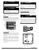
INSTALLATION IMPORTANT: Effective January 1, 2015, all split system and packaged air conditioners must be installed pursuant to applicable regional efficiency standards issued by the Department of Energy. ! NOTE: 18” (457.2 mm) clearance option described above is approved for outdoor units with wire grille coil guard only. Units with louver panels require 24” (609.6 mm) between units. On rooftop applications, locate unit at least 6 in. above roof surface. CAUTION 3/8–in. (9.53 mm) Dia.
Table 1 – Accessory Usage Standard No REQUIRED FOR SEA COAST APPLICATIONS (Within 2 miles / 3.
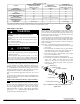
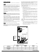
Table 2 – Refrigerant Connections and Recommended Liquid and Vapor Tube Diameters (In.) UNIT SIZE SERVICE VALVE VALVE CORE 18, 24 30, 36 42, 48 60 * A14236 Fig. 5 – Vapor Service Valve LIQUID Connection Tube Diameter Diameter 3/8 3/8 3/8 3/8 3/8 3/8 3/8 3/8 RATED VAPOR Connection Tube Diameter Diameter 5/8 3/4 7/8 7/8 5/8 3/4 7/8 1–1/8 Units are rated with 25 ft. (7.6 m) of lineset. See Product Data sheet for performance data when using different size and length linesets. Notes: 1.
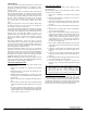
Make Electrical Connections CAUTION ! ! UNIT DAMAGE HAZARD Failure to follow this caution may result in equipment damage or improper operation. WARNING ELECTRICAL SHOCK HAZARD Installation of filter drier in liquid line is required. Failure to follow this warning could result in personal injury or death. Evacuate Refrigerant Tubing and Indoor Coil Do not supply power to unit with compressor terminal box cover removed.
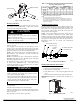
Table 3 – 3–Phase Monitor LED Indicators LED OFF FLASHING ON STATUS No call for compressor operation Reversed phase Normal Route 24v control wires through control wiring grommet and connect leads to control wiring. See Thermostat Installation Instructions for wiring specific unit combinations. (See Fig. 11.) Use No. 18 AWG color–coded, insulated (35°C minimum) wire. If thermostat is located more than 100 ft (30.5 m) from unit, as measured along the control voltage wires, use No.
Sequence of Operation Turn on power to indoor and outdoor units. Transformer is energized. Cooling On a call for cooling, thermostat makes circuits R–O and R–Y, and R–G. Circuit R–O energizes reversing valve, switching it to cooling position. Circuit R–Y energizes contactor, starting outdoor fan motor and compressor circuit. R–G energizes indoor unit blower relay, starting indoor blower motor on high speed. When thermostat is satisfied, its contacts open, de–energizing contactor and blower relay.
Check Charge Factory charge amount and desired subcooling are shown on unit rating plate. Additional subcooling may be required to achieve optimal heating performance based on the installed indoor unit. (see Table 5 or 6). Charging method is shown on information plate inside unit. For TXV, use subcooling method. For piston, use superheat method. To properly check or adjust charge, conditions must be favorable for subcooling or superheat charging.
Table 5 – Additional Subcooling Required − Model PH14NB Subcooling Delta from Rating Plate Value Outdoor Unit Tonnage Indoor Unit | Additional Subcooling Required 18 24 30 36 42 48 60 CAP**1814AL* - CAP**2414AL* - CAP**3014AL* - CAP**3614AL* - CAP**4221AL* - CAP**4817AL* +5 CAP**6021AL* - CAP**2414AL* - CAP**2417AL* - CAP**3017AL* - CAP**3617AL* - CAP**4224AL* - CAP**4821AL* +3 CAP**6024AL* - CAP**2417AL* - CAP**2517AL* +5 CAP**3614AL* - CAP**3621AL* - CAP**4321AL*
Table 6 – Additional Subcooling Required − Model PH15NB Subcooling Delta from Rating Plate Value Outdoor Unit Tonnage Indoor Unit | Additional Subcooling Required 18 24 30 36 42 48 60 CAP**1814AL* - CAP**2414AL* - CAP**3014AL* - CAP**3614AL* - CAP**4221AL* - CAP**4817AL* - CAP**6021AL* - CAP**2414AL* - CAP**2417AL* - CAP**3017AL* - CAP**3617AL* - CAP**4224AL* - CAP**4821AL* - CAP**6024AL* - CAP**2417AL* - CAP**2517AL* +5 CAP**3614AL* - CAP**3621AL* - CAP**4321AL*
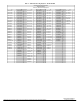
Table 7 – Required Liquid Line Temperatures _F LIQUID PRESSURE AT SERVICE VALVE (PSIG) 8 76 78 80 82 84 86 88 90 92 94 96 98 100 102 104 106 108 110 112 114 116 118 120 122 124 126 128 251 259 266 274 283 291 299 308 317 326 335 345 354 364 374 384 395 406 416 427 439 450 462 474 486 499 511 10 74 76 78 80 82 84 86 88 90 92 94 96 98 100 102 104 106 108 110 112 114 116 118 120 122 124 126 REQUIRED SUBCOOLING TEMPERATURE (°F) 12 14 72 70 74 72 76 74 78 76 80 78 82 80 84 82 86 84 88 86 90 88 92 90 94 92 96