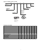
MODEL NUMBER NOMENCLATURE PH14 N B 018 00G B A 14 SEER Heat Pump with R --- 410A Refrigerant Series Variations Electrical Supply N=208/230--- 1 P=208/230--- 3 E=460/3 Variations 00G – Dense Grille Nominal Capacity 018 – 1–1/2 Tons 024 – 2 Tons 030 – 2–1/2 Tons 036 – 3 Tons 042 – 3–1/2 Tons 048 – 4 Tons 060 – 5 Tons B – R --- 410A Use of the AHRI Certified TM Mark indicates a manufacturer’s participation in the program For verification of certification for individual products, go to www.
PHYSICAL DATA 18--- A (N) UNIT SIZE SERIES 24--- A (N) 30--- A (N) 36--- B (N, P, E) 42--- A (N) 48--- A (N, P, E) 60--- A (N) 60--- A (P, E) Compressor Type Scroll REFRIGERANT R---410A Control TXV (R---410A Hard Shutoff) Outdoor Heating Piston # 42 46 49 57 61 65 73 78 Charge lb (kg) 5.30 (2.4) 5.60 (2.5) 6.40 (2.9) 7.67 (3.48) 8.25 (3.74) 8.68 (3.94) 10.60 (4.81) 10.60 (4.
REFRIGERANT PIPING LENGTH LIMITATIONS Maximum Line Lengths: The maximum allowable total equivalent length for heat pumps varies depending on the vertical separation. See the tables below for allowable lengths depending on whether the outdoor unit is on the same level, above or below the outdoor unit. Maximum Line Lengths for Heat Pump Applications MAXIMUM ACTUAL LENGTH ft (m) MAXIMUM EQUIVALENT LENGTH{ ft (m) MAXIMUM VERTICAL SEPARATION ft (m) Units on equal level 200 (61) 250 (76.
ACCESSORIES ORDER NUMBER DESCRIPTION Unit Size--- Series (Voltage) 18--- A (N) 24--- A (N) 30--- A (N) X X 36--- B (N) 36--- B (P) 36--- B (E) HC32GE234 Ball Bearing Fan Motor HC34GE240 Ball Bearing Fan Motor HC38GE219 Ball Bearing Fan Motor HC40GE228 Ball Bearing Fan Motor KAACH1601AAA Crankcase Heater Kit KAACH1701AAA Crankcase Heater Kit X X X X KAACS0201PTC PTC kit X X X X KAATD0101TDR Time Delay Relay X X X X X X KHAIR0201AAA Isolation Relay X X X X X KHAL
Accessory Description and Usage (Listed Alphabetically) 1. Ball--Bearing Fan Motor A fan motor with ball bearings which permits speed reduction while maintaining bearing lubrication. Usage Guideline: Required on all units when using MotorMasterr 2. Compressor Start Assist -- Capacitor and Relay Start capacitor and relay gives a hard boost to compressor motor at each start up.
Accessory Description and Usage (Listed Alphabetically) -- CONTINUED 14. Sound Hood Wraparound sound reducing cover for the compressor. Reduces the sound level by about 2 dBA. Usage Guideline: Suggested when unit is installed closer than 15 ft. (4.577 m) to quiet areas, bedrooms, etc. Suggested when unit is installed between two houses less than 10 ft. (3.05 m) apart. 15.
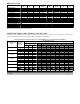
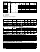
ELECTRICAL DATA UNIT SIZE --SERIES (VOLTAGE) V/PH OPER VOLTS* MAX COMPR MIN FAN LRA RLA MAX FUSE** or CKT BRK AMPS 20 25 30 30 40 40 50 20 25 30 15 15 15 MCA FLA 18--- A (N) 48.0 9.00 0.50 11.8 24--- A (N) 62.9 10.90 0.60 14.2 30--- A (N) 72.5 13.50 1.40 18.3 36--- B (N) 208/230/1 253 197 75.0 15.10 1.10 20.0 42--- A (N) 105.5 18.10 1.40 24.0 48--- A (N) 108.0 19.00 1.40 25.2 60--- A (N) 144.2 24.40 1.52 32.0 36--- B (P) 70.0 8.46 1.10 11.7 48--- A (P) 208/230/3 253 187 123.0 10.44 1.40 14.
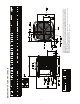
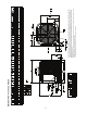
DIMENSIONS -- ENGLISH SINGLE PHASE When installing, allow sufficient space for airflow clearance, wiring, refrigerant piping, and service. Allow 24 in. (609.6 mm) clearance to service end of unit and 48 in. (1219.2 mm) (above unit. For proper airflow, a 6–in. (152.4 mm) clearance on 1 side of unit and 12–in. (304.8 mm) on all remaining sides must be maintained. Maintain a distance of 24 in. (609.6 mm) between units or 18 in. (457.2 mm) if no overhang within 12 ft. (3.
DIMENSIONS -- SI SINGLE PHASE When installing, allow sufficient space for airflow clearance, wiring, refrigerant piping, and service. Allow 24 in. (609.6 mm) clearance to service end of unit and 48 in. (1219.2 mm) (above unit. For proper airflow, a 6–in. (152.4 mm) clearance on 1 side of unit and 12–in. (304.8 mm) on all remaining sides must be maintained. Maintain a distance of 24 in. (609.6 mm) between units or 18 in. (457.2 mm) if no overhang within 12 ft. (3.
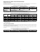
A A PH14PB04800GBAAB PH14PB06000GBAAB 36,48,60 - 792.5 792.5 792.5 31 3/16 N 31 3/16 Y=YES N=NO N N 31 3/16 N N 792.5 N Y Y Y 792.5 31 3/16 N Y 31 3/16 N Y N N N N N INCH 32 1/16 28 11/16 28 11/16 32 1/16 28 11/16 28 11/16 B 23 1/8 25 3/4 31 3/16 35 587.3 654.0 792.5 889.0 17 20 22 26 7/8 7/16 15/16 3/4 454.6 518.5 583.2 679.7 "Y" A PH14PB03600GBAAB N N MM 792.
24” (609.6) Service 12” (304.8) Note: Numbers in ( ) = mm 18” (457.2) 24” (609.6) Service Wall 6” (152.4) 18” (457.2) 12” (304.8) 24” (609.6) Service Wall 18” (457.2) 12” (304.8) Clearances (various examples) 24” (609.6) Service 12” (304.8) 24” (609.6) Service Wall 6” (152.4) IMPORTANT: When installing multiple units in an alcove, roof well, or partially enclosed area, ensure there is adequate ventilation to prevent re--circulation of discharge air.
BUILDING HEAT LOSS, UNIT INTEGRATED HEATING CAPACITY, MBTUH 0 0 C F 0 10 20 30 40 50 60 70 80 -23.3 -10.0 -17.8 0.0 BALANCE POINT WORKSHEET -12.2 10.0 -6.7 20.0 4.4 40.0 OUTDOOR TEMPERATURE -1.1 30.0 PH14NB042 10.0 50.0 15.6 60.0 21.1 70.0 BASED ON INDOOR ENTERING AIR AT 70◦F (21.1◦C) AND AT RATED CFM PH14NB018 FB4CNP018L PH14NB024 FB4CNP030L PH14NB030 FB4CNP030L PH14NB036 FB4CNP036L FB4CNP042L 80.0 26.7 0.0 2.9 5.9 8.8 11.7 14.6 17.
TESTED AHRI COMBINATION RATINGS NOTE: Ratings contained in this document are subject to change at any time. For AHRI ratings certificates, please refer to the AHRI directory www.ahridirectory.org Additional ratings and system combinations can be accessed via the Payne database at: www.MyPayneRatings.com High Temp Model Number Indoor Coil Model Number Cooling Capacity EER SEER E Capacity E COP PH14NB018---A FB4CNP018L 17,800 11.7 14 17,600 PH14NB024---A FB4CNP030L 22,200 11.
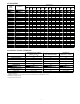
72 (22.2) 67 (19.4) 63 (17.2)†† 62 (16.7) 57 (13.9) 72 (22.2) 67 (19.4) 63 (17.2)†† 62 (16.7) 57 (13.9) 72 (22.2) 67 (19.4) 63 (17.2)†† 62 (16.7) 57 (13.9) 72 (22.2) 67 (19.4) 63 (17.2)†† 62 (16.7) 57 (13.9) 72 (22.2) 67 (19.4) 63 (17.2)†† 62 (16.7) 57 (13.9) 72 (22.2) 67 (19.4) 63 (17.2)†† 62 (16.7) 57 (13.9) 72 (22.2) 67 (19.4) 63 (17.2)†† 62 (16.7) 57 (13.9) 72 (22.2) 67 (19.4) 63 (17.2)†† 62 (16.7) 57 (13.9) 72 (22.2) 67 (19.4) 63 (17.2)†† 62 (16.7) 57 (13.
72 (22.2) 67 (19.4) 63 (17.2)†† 62 (16.7) 57 (13.9) 72 (22.2) 67 (19.4) 63 (17.2)†† 62 (16.7) 57 (13.9) 72 (22.2) 67 (19.4) 63 (17.2)†† 62 (16.7) 57 (13.9) 72 (22.2) 67 (19.4) 63 (17.2)†† 62 (16.7) 57 (13.9) 72 (22.2) 67 (19.4) 63 (17.2)†† 62 (16.7) 57 (13.9) 72 (22.2) 67 (19.4) 63 (17.2)†† 62 (16.7) 57 (13.9) EWB 72 (22.2) 67 (19.4) 63 (17.2)†† 62 (16.7) 57 (13.9) 72 (22.2) 67 (19.4) 63 (17.2)†† 62 (16.7) 57 (13.9) 72 (22.2) 67 (19.4) 63 (17.2)†† 62 (16.7) 57 (13.
72 (22.2) 67 (19.4) 63 (17.2)†† 62 (16.7) 57 (13.9) 72 (22.2) 67 (19.4) 63 (17.2)†† 62 (16.7) 57 (13.9) 72 (22.2) 67 (19.4) 63 (17.2)†† 62 (16.7) 57 (13.9) 72 (22.2) 67 (19.4) 63 (17.2)†† 62 (16.7) 57 (13.9) 72 (22.2) 67 (19.4) 63 (17.2)†† 62 (16.7) 57 (13.9) 72 (22.2) 67 (19.4) 63 (17.2)†† 62 (16.7) 57 (13.9) 75 (23.9) 28.05 34.45 33.15 40.65 44.33 29.37 36.59 35.15 43.44 46.14 30.65 38.69 37.10 45.92 47.65 Sens‡ 64.47 58.76 54.60 53.59 51.87 65.61 59.86 55.66 54.79 53.97 66.47 60.67 56.46 55.
75 75 (23.9) 11.92 12.15 1350 11.66 1050 1200 12.80 1350 12.30 1050 12.56 13.43 1350 1200 13.19 12.92 1050 1200 9.95 1125 9.61 875 9.86 10.44 1125 1050 10.34 1050 10.08 10.91 1125 875 10.81 10.54 875 1050 7.55 900 7.30 700 7.44 7.96 900 800 7.84 7.69 700 800 8.35 900 8.09 700 8.23 4.84 675 800 4.74 4.65 525 600 5.16 675 4.98 525 5.08 5.44 675 600 5.36 11.18 10.97 10.73 11.77 11.56 11.32 12.35 12.13 11.89 9.16 9.07 8.84 9.
20.74 21.08 19.58 19.94 20.28 2000 2250 1750 2000 2250 17.00 1800 20.38 16.69 1600 1750 16.35 1400 21.84 14.51 1575 2250 14.27 1400 21.51 14.00 1225 21.14 15.33 1575 2000 15.07 1400 1750 14.78 1225 13.58 16.19 1575 1800 15.91 1400 13.37 15.59 1225 1600 10.17 1350 13.11 9.95 1200 1400 9.70 1050 16.05 10.93 1350 1800 10.70 1200 15.80 10.46 1050 1600 11.64 1350 15.48 11.41 1200 1400 11.16 Total 18.65 18.35 18.01 19.40 19.08 18.
GUIDE SPECIFICATIONS GENERAL System Description AIR--COOLED, SPLIT--SYSTEM HEAT PUMP PH14*B 1--1/2 TO 5 NOMINAL TONS Fans Outdoor--mounted, air--cooled, split--system heat pump unit suitable for ground or rooftop installation. Unit consists of a hermetic compressor, an air--cooled coil, propeller--type condenser fan, and a control box. Unit will discharge supply air upward as shown on contract drawings. Unit will be used in a refrigeration circuit to match up to a packaged fan coil or coil unit.
SYSTEM DESIGN SUMMARY 1. 2. 3. 4. 5. 6. 7. 8. 9. 10. 11. Intended for outdoor installation with free air inlet and outlet. Outdoor fan external static pressure available is less than 0.01--in. wc. Minimum outdoor operating air temperature without low--ambient operation accessory is 55_F (12.8_C). Maximum outdoor operating air temperature for cooling mode is 125_F (51.7_C). Minimum outdoor operating air temperature for heating mode is –30_F (–34.4_C).