EM316EDFA-BR Erbium Doped Fiber Amplifier Booster EM316EDFA-LPR Erbium Doped Fiber Inline Pre-Amplifier User Guide 1294008-001 Revision D2 January 28, 2008
Fiber Driver® EM316EDFA User Guide Table of Contents 1 Preliminary Considerations .............................................................. iii 1.1 Trademarks ...................................................................................................................................................iii 1.2 Copyright.......................................................................................................................................................iii 1.3 Customer Support.......
Fiber Driver® EM316EDFA User Guide 5.2.4 Chassis Context .................................................................................................................................. 18 5.2.4.1 “show” ...........................................................................................................................18 5.2.4.2 Other Commands..........................................................................................................19 5.2.5 Slot Context Commands and Examples.......
Fiber Driver® EM316EDFA User Guide 1 Preliminary Considerations 1.1 Trademarks All trademarks are the property of their respective holders. 1.2 Copyright MRV Communications reserves the right to change technical specifications or documentation in order to improve reliability, function, or design. Exercise discretion in using this document. The user assumes sole responsibility for applying the information supplied herein. Copyright © 2007 by MRV Communications. All rights reserved. 1.
Fiber Driver® EM316EDFA User Guide 1.4 Compliance Contact your sales representative for more regulatory compliance information regarding specific MRV products or product families.
Fiber Driver® EM316EDFA User Guide 1.5 General Safety 1.5.1 Cautions and Warnings Disconnect all power from electronic devices before servicing. Some equipment may have multiple power cords requiring disconnection. 1.5.2 Laser Safety WARNING: Fiber optic equipment may emit laser or infrared light that can injure your eyes. Never look into an optical fiber or connector port. Always assume that fiber optic cables are connected to a laser light source.
Fiber Driver® EM316EDFA User Guide 1.5.3 Laser Device Classifications Laser devices of class 1M, class 2, class 2M and class 3R Precautionary measures are only necessary to avoid a permanent direct looking into the laser beam; for classes 2 and 2M is a momentary (0.25 sec.) irradiation in a wave length range between 400 nm and 700 nm, as it may occur when you accidentally look into the beam, not considered to be dangerous. However, you should not level the laser beam intentionally at people.
Fiber Driver® EM316EDFA User Guide 1.5.4 Static Electricity Eliminate static electricity in the workplace by grounding operators, equipment, and devices including components and computer boards. Grounding prevents static charge buildup and electrostatic potential differences. Transporting products in special electrostatic shielding packages reduces electrical field damage potential. 1.5.5 Workplace Preparation A safe and effective workplace provides the following items.
Fiber Driver® EM316EDFA User Guide 1.6 About This Manual Document Number: P/N 1294008-001 Rev D2 Document: EM316EDFA-BR / EM316EDFA-LPR User Guide Release Date: January 28, 2008, 4:26:01 PM 1.7 Latest Revision and Related Documents The latest revision of MRV documents may be found at: http://www.mrv.com Release Notes for Fiber Driver modules are produced as required.
Fiber Driver® EM316EDFA User Guide 2 Introduction to EM316EDFA Optical Amplifiers The fiber optic amplifier module is used to increase an optical signal for extended range or clarity without electrical conversion circuitry. The MRV EM316EDFA modules boost an optical input up to 20 decibels. The amplifier also has a bandwidth of 40 nm, making it suitable for use in wavelength division multiplexing (WDM) applications as an optical spectral amplifier.
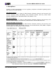
Fiber Driver® EM316EDFA User Guide 2.1 Features The EM316EDFA board can run in standalone mode without any input from a management module. The EM316EDFA analog input power determines the output power because the module runs at a fixed gain. EM316EDFA status is reported through SNMP through a network management module as well as by LEDs on the front panel. The green “SD” LED on the front panel indicates input greater than the thresholds corresponding to the EDFA module type, as indicated in the table below.
Fiber Driver® EM316EDFA User Guide 3 Preparation and Installation 3.1 Unpacking the Fiber Driver Module Follow these steps with reference to the figure below. Step 1. Open the cardboard box Step 2. Remove the static bag containing the device. Step 3. Check for additional accessories in the box that may move beneath the module tray during transit. In the unlikely event that any package content is missing, contact an authorized MRV dealer or representative.
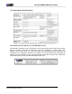
Fiber Driver® EM316EDFA User Guide 3.2 Front Panel Figure 3 -- EM316EM316EDFA-BR / EM316EDFA-LPR Front Panel 3.3 LEDs PWR/NMS Power SD Input Optical Power OPTICAL OUTPUT OK Output Optical Power On – DC +5V power is applied to the card On – Input signal greater than the input threshold setting On – Output power is greater than -2 dBm, for apc mode or -10 dBm for agc mode 3.4 DIP Switches The EM316EDFA-BR is pre-configured in booster mode. There are no user-selectable switches.
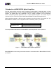
Fiber Driver® EM316EDFA User Guide 3.5 Module Installation EM316xx cards are hot-swappable in a powered Fiber Driver chassis. Install the EM316xx module by aligning the edge of the card with the rail of the chassis slot. Hand-tighten the thumb screw. Do not over-tighten. The thumb screw is on the left when installed in the BU-1, BU-2, BU-3, and BU-4 chassis. The thumb screw is on the bottom when installed in the BU-16 chassis. 3.5.1.1.
Fiber Driver® EM316EDFA User Guide Step 2 Install the module into a Fiber Driver chassis by aligning the edge of the card with the rail of the chassis. Tighten the thumbscrew by hand. Figure 5 -- Module installation (not all chassis are shown) Handle modules by the edges to avoid damaging any components. Follow all ESD precautions listed at the front of this manual. Use your thumb to push the module securely into the chassis slot.
Fiber Driver® EM316EDFA User Guide 4 EDFA Features While operating correctly in an appropriate environment, EM316EDFA optical amplifier modules require minimal operator intervention. However, because these devices are critical to network infrastructure, administrative monitoring of these devices is essential for early fault detection. EM316EDFA modules report simple status visually with front panel LEDs.
Fiber Driver® EM316EDFA User Guide 4.1.1 Management Control from the Network • • • • • • • • • Output power or gain control Power or gain control limits Input power and output power readings Output gain reading Case temperature reading Alarm status including case temperature, loss of input power, loss of output power Amplifier status reading Software reset Output power mute 4.1.2 EM316EDFA Alarm Output Pins • • • Case temperature Loss of input Loss of output 4.1.
Fiber Driver® EM316EDFA User Guide 5 Module Management Most Fiber Driver modules, including the EDFA amplifier family, may be managed by a Fiber Driver network management (NM) module installed in the same chassis. The EDFA amplifier modules may be managed by the EM316LNXNM-OT Network Management (NM) module. The NM module installs in the same chassis as the managed modules. It provides management for the EDFA amplifier module and other compatible Fiber Driver modules resident in the chassis.
Fiber Driver® EM316EDFA User Guide 5.1 Serial Console Interface After the network management (NM) module is installed, power up the chassis and attach the serial RS-232 cable to the PC or terminal device. Configuring terminal emulation software on the PC is beyond the scope of this document. The components below may be ordered from MRV.
Fiber Driver® EM316EDFA User Guide 5.2 EM316LNXNM-OT Command Line Interface (CLI) The EM316LNXNM-OT provides command line interface (CLI), SNMP, and graphical administration options for a Fiber Driver chassis system. This section introduces the CLI for the Linux-based network management (EM316LNXNM-OT) module. EM316LNXNM-OT management commands are specific to each module.
Fiber Driver® EM316EDFA User Guide 5.2.1 EM316LNXNM-OT Boot and CLI Login The box below shows the NM boot and login to the built-in admin user account. The “banner” information that displays after the login may also be displayed from the CLI prompt with the show version command. The show command is introduced in a later section. Refer to EM316LNXNM-OT documentation for network manager and CLI configuration help. U-Boot 1.0.
Fiber Driver® EM316EDFA User Guide 5.2.2 CLI Navigation The CLI uses five operational contexts: login, configuration, chassis, slot, and port. Only the login context is not considered a configuration mode. The system prompt includes a string to indicate the current operational context, as illustrated in the example below. The “#” character ends the prompt string, and a space separates the command from the prompt. Each navigation command in the box below is bold for emphasis in print only.
Fiber Driver® EM316EDFA User Guide 5.2.3 Login Context Commands and Examples The login context refers to the only CLI state not considered a configuration context. Commands in this context are generally for system status monitoring. Use the “?” and “list” commands at the fiberdriver # prompt to display the list of command line options. These help commands are shown in the slot and port command illustrations later in this section. A few login context commands are illustrated in this section. 5.2.3.
Fiber Driver® EM316EDFA User Guide 5.2.3.3 “show running-config” The show running-config command displays the currently active system parameters for the management system. fiberdriver# show running-config Building configuration... Current configuration: ! ! Configuration saved on 2005/01/04 22:39:51 ! ! Configuration written by admin! ! ! EM316LNXNM-OT v4.0 fdr 54 (Jun 8 2007 - 15:57:38). ! U-Boot 1.0.1 (Jan 25 2005 - 11:08:25). ! Linux kernel v2.4.26 (#1 Wed Dec 13 10:36:44 PST 2006).
Fiber Driver® EM316EDFA User Guide 5.2.3.4 “show startup-config” The show startup-config command displays the contents of the startup-config file that are applied when the system boots. Default values are applied to any parameters not specified in this file. fiberdriver# show startup-config ! ! Configuration saved on 2005/01/04 21:15:03 ! ! ! Configuration written by admin! ! ! EM316LNXNM-OT v4.0 fdr 54 (Jun 8 2007 - 15:57:38). ! U-Boot 1.0.1 (Jan 25 2005 - 11:08:25). ! Linux kernel v2.4.
Fiber Driver® EM316EDFA User Guide 5.2.3.5 Configuring System Parameters Enter "configuration" mode, as shown below, to configure the system parameters fiberdriver# configure terminal Note that each command is completed with the or key, which is not printable. Once the mode is changed, the prompt also changes. Change the SUPER user password using the "username" command. fiberdriver(config)# username admin password Set the IP configuration using the "ip" command group.
Fiber Driver® EM316EDFA User Guide 5.2.4 Chassis Context Command examples in this section are applied in the chassis-level context. The box below shows the command to navigate to the chassis context from the login context. fiberdriver# configure terminal fiberdriver(config)# fiberdriver(config)# chassis 1 fiberdriver(chassis/1)# 5.2.4.1 “show” The following CLI excerpt shows a Fiber Driver chassis system with an EDFA amplifier module and an EM316LNXNM-OT network management (NM) module.
Fiber Driver® EM316EDFA User Guide 5.2.4.2 Other Commands The commands available at the chassis level are consistent in Fiber Driver environments. These general system features are beyond the scope of this document. A list of available commands in the chassis context is displayed by typing “?” or “list” at the prompt.
Fiber Driver® EM316EDFA User Guide 5.2.5 Slot Context Commands and Examples The table below lists commands that relate specifically to the EDFA modules in the slot-level command context of the EM316LNXNM-OT command line interface (CLI). Some sample commands are illustrated in this section following the command table.
Fiber Driver® EM316EDFA User Guide 5.2.5.1 “?” The “?” is a special help character in the EM316LNXNM-OT command line. In previous releases, the “?” character did not echo to the display when typed. Beginning in version 4.0, the “?” displays as other commands do. Results of the help request are displayed immediately to the monitor. The box below shows the output of the “?” typed alone on the command line in the slot-level configuration context.
Fiber Driver® EM316EDFA User Guide 5.2.5.2 “list” The list command displays all the full command options (including applicable command line arguments) available in the current context. The box below illustrates the display in the slot-level context specific to EDFA modules. fiberdriver(slot/1.3)# list clear-type default all default description default me description .LINE echo echo .
Fiber Driver® EM316EDFA User Guide 5.2.5.3 “show” The show command displays management and system information related to the EM316LNXNM-OT management module, the hosting chassis, other modules in the chassis, and ports available within the managed system. The arguments (parameters) following the show command and the operational context displayed by the system prompt control the many functions available through this command.
Fiber Driver® EM316EDFA User Guide The boxes below illustrate two common parameters used with the show command. Default settings are listed in the show defaults command output. These parameters reflect the module boot configuration which is determined by DIP switches and firmware programming. All lines in this display begin with “!” to indicate that they are comments for information only. fiberdriver(slot/1.3)# show defaults slot 1.3 ! description EM316EDFAv at 1.3 fiberdriver(slot/1.3)# slot 1.
Fiber Driver® EM316EDFA User Guide Each module may be given a descriptive name with the command below. The show command follows with the new name bolded. Each new slot name may also be displayed with individual show commands in each slot context. fiberdriver(slot/1.3)# description EDFA-1 fiberdriver(slot/1.4)# description EDFA-2 fiberdriver(slot/1.
Fiber Driver® EM316EDFA User Guide 5.2.6 Port Context Commands and Examples The table below lists commands that relate specifically to EDFA modules in the port-level command context of the EM316LNXNM-OT command line interface (CLI). Some sample commands are illustrated in this section following the command table. A specific command list for each context is displayed by typing the “?” command at any prompt.
Fiber Driver® EM316EDFA User Guide Command examples in this section are applied in the port-level context. The box below shows the command to navigate to a specific port context from the login context. fiberdriver# configure terminal fiberdriver(config)# port 1.3.1 fiberdriver(port/1.3.1)# 5.2.6.1 “?” The “?” command, used alone on the command line, lists the commands available in the current operational context.
Fiber Driver® EM316EDFA User Guide The box below shows the output of the “?” typed alone on the command line in the port-level configuration context. The box below is specific to the EDFA modules. fiberdriver(port/1.3.
Fiber Driver® EM316EDFA User Guide 5.2.6.2 “list” The list command displays all the full command options (including applicable command line arguments) available in the current context. The box below illustrates the display at the port-level context specific to the EDFA modules. fiberdriver(port/1.3.1)# list default all default description default me default protocol default rm-chassis default rm-port default rm-slot default shutdown description .LINE echo echo .
Fiber Driver® EM316EDFA User Guide 5.2.6.3 “show” The show command displays management and system information related to the EM316LNXNM-OT management module, the hosting chassis, other modules in the chassis, and ports available within the managed system. The arguments (parameters) following the show command and the operational context displayed by the system prompt control the many functions available through this command. The box below illustrates the show command.
Fiber Driver® EM316EDFA User Guide 5.2.6.4 “port description” As with a module at the slot level, a descriptive name may be applied to each port. An example of the description command at the port level is shown below. fiberdriver(port/1.3.1)# description EDFA-port1 fiberdriver(port/1.3.1)# show Port: 1.3.1 Name: EDFA-port1 Enable: enable Link: no Signal Connector: fo SC Medium: single Mode TxPower(dBm): -15.26 DDiags: Alarm Temp(C): 23 Supply(V): 3.28 Alarm Cause: TX Loss of Signal Alarm (tx -15.
Fiber Driver® EM316EDFA User Guide 5.2.7 Displaying and Saving System Parameters Use the write terminal command to display the current operating parameters. fiberdriver(port/1.3.1)# write terminal Building configuration... Current configuration: ! ! Configuration saved on 2005/01/04 21:11:06 ! ! ! Configuration written by admin! ! ! EM316LNXNM-OT v4.0 fdr 54 (Jun 8 2007 - 15:57:38). ! U-Boot 1.0.1 (Jan 25 2005 - 11:08:25). ! Linux kernel v2.4.26 (#1 Wed Dec 13 10:36:44 PST 2006). ! EM316LNXNM (firmware 5c.
Fiber Driver® EM316EDFA User Guide 5.2.8 Restoring Default Parameters Use the default command to discard changes applied to the module configuration. The example below illustrates returning the entire module to the original factory defaults. Use the “?” after the default command or refer to EM316LNXNM-OT documentation for parameters to reapply only selected default values including individual port settings. The command below is applied in the main configuration context.
Fiber Driver® EM316EDFA User Guide 6 Appendix These sections contain technical and support information for the EM316EDFA modules. 6.1 Technical Specifications Operating Temperature Range 0° C to 45° C (32° F to 113° F) Storage Temperature -10° C to 60° C (-14° F to 140° F) Relative Humidity 85% maximum, non-condensing Physical Dimensions 50 mm x 75 mm x 175 mm deep (1" x 3" x 7" deep) Weight 14.4 ounces (408 grams) Power 5V DC @ 2A maximum Cooling Air 1 inch clearance for external vents 6.
MRV Communications, Inc. 20415 Nordhoff Street Chatsworth, CA 91311 Tel: 818-773-0900 Fax: 818-773-0906 http://www.mrv.