
User manual


MRV Communications, Inc. – Installation Manual
47
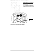
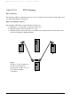
Figure E.3: Active Transmitters (Shown Darkened).
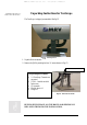
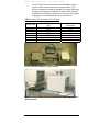
Figure E.2b: Bench Test setup drawing
for 10” TS model.
Note that one device is higher than the
other and shifted over to the side so that
only one transmitter from each device is
facing opposite the other device’s receiver.
Telescopes