TereScope700 and TereScope800 Wireless Optical Communication Links Models TS700/100, TS700/155, TS700/G, TS800/155 UserManual
WIRELESS OPTICAL COMMUNICATIONS User Manual Document Number ML48237 (4703700), Rev. 4.0 February 2006 MRV Communications, Inc. Web site: www. mrv.
M R V C o mmu n i c a t i o n s , I n c . – I n s t a l l a t i o n M a n u a l Table of Contents STANDARDS Standards Compliance ............................................................................ i FCC Notice ............................................................................................... i CE Mark ................................................................................................... i Other Standards ...............................................................
M R V C o mmu n i c a t i o n s , I n c . – I n s t a l l a t i o n M a n u a l Data/Signal Cabling .............................................................................. 24 For TS700/155, TS700/G, TS800/155, TS800/155-F............................24 For TS700/100.........................................................................................25 CHAPTER 4 - BENCH TEST TS700/155, TS800/155, and TS800/155-F............................................ 26 TS700/100 ........................
M R V C o mmu n i c a t i o n s , I n c . – I n s t a l l a t i o n M a n u a l Standards Standards Compliance UL 1950; CSA 22.2 No 950; FCC Part 15 Class B; CE-89/336/EEC, 73/23/EEC FCC Notice WARNING: This equipment has been tested and found to comply with the limits for a Class B digital device, pursuant to Part 15 of the FCC Rules. These limits are designed to provide reasonable protection against harmful interference when the equipment is operated in a commercial environment.
M R V C o mmu n i c a t i o n s , I n c . – I n s t a l l a t i o n M a n u a l Other Standards 1. CISPR 22: 1993 AS/NZS 3548: 1995, Class B Joint Amendment No. 1: 1997, Joint Amendment No. 2: 1997 2. EN 60950+A1+A2+A3+A4+A11 ACA TS001-1997 AS/NZS 3260: 1993 A4: 1997 3. ITU G.703, G.704, G.706,G.736, G.737, G.738, G739, G740, G.775, G.823.
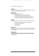
M R V C o mmu n i c a t i o n s , I n c . – I n s t a l l a t i o n M a n u a l About this User Manual Audience This manual is intended for the user who wishes to install, operate, manage and troubleshoot the TereScope700 and TereScope800.
M R V C o mmu n i c a t i o n s , I n c . – I n s t a l l a t i o n M a n u a l Safety Requirements All requirements stipulated in the safety laws of the country of installation must be abided by when installing the TereScopes. Caution! In addition, ensure that the requirements noted in this chapter are met in order to reduce risk of electrical shock and fire and to maintain proper operation. Before Installing Power: Ensure that all power to the TereScope is cut off.
M R V • • C o mmu n i c a t i o n s , I n c . – I n s t a l l a t i o n M a n u a l casual passersby. Examples of restricted locations are: sides of buildings at sufficient heights, restricted rooftops, and telephone poles. This definition of a restricted location is in accordance with the proposed IEC 60825-I Part 12 requirements. Avoid using controls, adjustments, or procedures other than those specified herein as they may result in hazardous radiation exposure.
M R V C o mmu n i c a t i o n s , I n c . – I n s t a l l a t i o n M a n u a l Introduction CAREFULLY READ THE ENTIRE MANUAL BEFORE INSTALLING A n InfraRed (IR) link allows connection without any cable between two distant sites. For that, two identical transceivers, each installed on one site and aligned to face each other, provide point-to-point connectivity.
M R V C o mmu n i c a t i o n s , I n c . – I n s t a l l a t i o n M a n u a l Chapter 1 The Product Caution! When handling the TereScope, take special care not to damage the polycarbonate window! Models Table 1: Models of the TereScope1 Models Part Number Description TS700/100 TS100/A/FET/VS TereScope700 for Fast Ethernet 100Base-TX connectivity up to a distance of 360 m + Power-over-Ethernet option.
M R V C o mmu n i c a t i o n s , I n c . – I n s t a l l a t i o n M a n u a l S (for SingleMode) ‘U’ represents operating wavelength. Instead of U use one of the following: 8 (for 850 nm) 3 (for 1310 nm) 5 (for 1550 nm) ‘W’ represents connector type. Instead of W use one of the following: C (for SC) T (for ST) ‘FET’ (Fast ethernet) represents 100Base-TX with RJ45 connector ‘V’ represents existence/absence of Fusion. Instead of V use one of the following: V designates no built-in Fusion option.
M R V C o mmu n i c a t i o n s , I n c . – I n s t a l l a t i o n M a n u a l 2. Back All models of the TereScope are SNMP manageable. SNMP monitoring can be performed using MRV’s MegaVision SNMP management application. A. TS700/155 (Standard Model) The TS700 supports Fast Ethernet, OC3, STM1, E3, and T3 protocols in the 34155 Mbps range.
M R V C o mmu n i c a t i o n s , I n c . – I n s t a l l a t i o n M a n u a l Back Panel Description Table 2: TS700/155 Standard Model Back Panel Controls, Interfaces, and Indicators Connectors Selectors (DIP Switch Toggles) -shown in Figure 1.3 Indicators (7-segment display, LEDs) Alignment Power Power source Terminal Block (Main or UPS) AC power supply (100 to 240 Vac) or DC power supply (24 to 60 Vdc) Fiber optic Fiber Optic interface for connection to the peripheral equipment.
M R V C o mmu n i c a t i o n s , I n c . – I n s t a l l a t i o n M a n u a l B. TS800/155 Standard Model The TS800/155 supports most of the prevalent protocols in the 34-155 Mbps range. Support for a special protocol, which is not on the list, can be ordered after coordination with the factory. This model can be used for Open Protocol applications which ensures complete transparency (including all data in the range of 1-155 Mbps.) In this case, a maximum 2 dB of the power budget is lost. Figure 1.
M R V C o mmu n i c a t i o n s , I n c . Selectors (DIP Switch DS1 Toggles) -- shown in Figure 1.3and 1.4 Data Rate (Toggles 1,2,3,4) Selectors (DIP Switch DS2 Toggles) -- shown in Figure 1.3 and 1.4 Mode Select (Toggles 1, 2, 3) Laser Power Off (Toggle 4) Fusion (Toggle 5) Window Heater (Optional) (Toggle 6) IP address set up (Toggle 7) Control Mode (Toggle 8) – I n s t a l l a t i o n M a n u a l Set the transmission rate of the transceiver (internal clock).
M R V C o mmu n i c a t i o n s , Indicators (7-segment display and LEDs) Alignment I n c . – I n s t a l l a t i o n M a n u a l Air RX Flag LED Green LED indicates data received by the Airlink receiver. Turns ON at the threshold level. Air RX Sync LED Yellow LED. Turns ON if the rate of the received Data matches the Data Rate set on the Data Rate DIP switch. F/O Main, RX Flag LED Upper green LED indicates Data received by the Fiber Optic receiver. Turns ON at the threshold level.
M R V C o mmu n i c a t i o n s , I n c . – I n s t a l l a t i o n M a n u a l C. TS800/155-F (Standard Model including Fusion option) Figure 1.4: TS800/155-F Standard Model Panel Schematic This special TS800/155-F model can be connected to the back-up radio system without a special MRV switch and card supporting Fusion.
M R V That’s what happens when the air channel is interrupted. C o mmu n i c a t i o n s , TS I n c . – I n s t a l l a t i o n M a n u a l TS IR = 100 Mbps Main F/O F/O Main Redundant RF Transceiver RF Transceiver RF = 2-10 Mbps F/O 10 Base-T STP F/O Redundant Switch 10/100 Base-T MC 10/100TX-100FX Media Converter Network Network 10 Base-T STP Figure 1.
M R V C o mmu n i c a t i o n s , I n c . – I n s t a l l a t i o n M a n u a l Fusion Maximizing Link Availability in All Weather Conditions. The TereScope Fusion was designed to combine the best features of two transport mediums, laser light and radio waves, to form a single, seamless, wireless communication link between network devices. By leveraging both technologies, we can provide the 99.999% availability that your network requires. Protocol: Frequency: 10Base-T (IEEE 802.1 1 b) 2.4 - 2.
M R V C o mmu n i c a t i o n s , I n c . – I n s t a l l a t i o n M a n u a l D. TS700/100 - Fast-Ethernet System Figure 1.6: TS700/100 Model Back Panel Back Panel Description Table 4: TS700/100 Back Panel Controls, Interfaces, and Indicators Connectors Power Power source Terminal Block (Main or UPS) AC power supply (100 to 240 Vac) or DC power supply (24 to 60 Vdc). 100Base-TX Copper interface (RJ45) for STP cables. MDI-X connection (TX: pins 3,6 and RX: pins 1,2).
M R V C o mmu n i c a t i o n s , Selectors (DIP Switch Toggles) -shown in Figure 1.6 Indicators (7-segment display, LEDs) Alignment I n c . – I n s t a l l a t i o n M a n u a l Mode of Operation (Toggles 1, 2) Set the Operating Mode ALIGNMENT = Idle transmitted automatically NORMAL = Signal received through the TP port is transmitted through the Airlink TX. Signal received through the Airlink RX is transmitted through the TP TX.
M R V C o mmu n i c a t i o n s , I n c . – I n s t a l l a t i o n M a n u a l E. TS700/G - Gigabit-Ethernet System The TereScope 700/G supports Gigabit Ethernet and FiberChannel protocols. The physical design and configuration of the TS700/G is similar to the other members of the series, and its operational principles are essentially the same. However, The TS700/G only offers a duplex fiber interface. The standard is 850nm SC multimode.
M R V C o mmu n i c a t i o n s , Selectors (DIP Switch Toggles) -shown in Figure 1.7 Indicators (7-segment display, LEDs),Dry Contact Alarms Alignment I n c . – I n s t a l l a t i o n M a n u a l Transmitter Mode (Toggle 1) ON position (up) for links above 150m distance. OFF position (down) is for under 170m distance Not Used (Toggle 2) Not used. (No internal loopback function.
M R V C o mmu n i c a t i o n s , I n c . – I n s t a l l a t i o n M a n u a l Monitoring and Management options 1 – Management The TS is manageable by using SNMP option. SNMP monitoring can be performed via MegaVision, MRV’s SNMP software. RJ45 Connection for SMNP Interface Figure 1.8: SNMP + TS 2 - Dry contact (Only TS800) The TS can be connected to dry contact box (RSM-DC). The RSM-DC is directly attached to TS at "Remote Monitor" connector. RSM-DC Figure 1.
M R V C o mmu n i c a t i o n s , I n c . – I n s t a l l a t i o n M a n u a l Typical Connection 1 - Fiber Connection In order to implement a connection, each transceiver must be connected to the peripheral/testing equipment through fiber optic cables. A correct connection is indicated by the display on the back panel of the transceiver (see the section Display and Results pages 29 and 30).
M R V C o mmu n i c a t i o n s , I n c . – I n s t a l l a t i o n M a n u a l Chapter 2 Site Survey The first step before every installation is to visit the sites to be linked. in order to make sure that the connection is feasible, to find out potential obstacles or difficulties and to decide on the location and mounting points of the transceivers. Line of Sight A necessary condition for linking two distant buildings is that the two mounting sites must be within clear sight of each other.
M R V (1) In case such situations cannot be avoided, special mounting accessories and techniques must be designed and considered (see section Particular Figure Cases\Techniques page 37) & C o mmu n i c a t i o n s , Prefer Concrete Parapet Structural wall or column I n c . – I n s t a l l a t i o n Avoid Old constructions Soft material (asphalt, etc.
M R V C o mmu n i c a t i o n s , I n c . – I n s t a l l a t i o n M a n u a l Figure 2.1: Optimal Mounting TereScope at edge of roof so that heat rising from roof surface does not affect beam Beam path more than 4.5 m (15 ft) above surface to avoid traffic and rising heat. Figure 2.2: Acceptable Mounting Figure 2.3 shows an unrecommended TereScope link location because of interference by IR. Notice that the TereScopes are mounted far from the rooftop edges or are too close to the ground.
M R V C o mmu n i c a t i o n s , I n c . – I n s t a l l a t i o n M a n u a l Figure 2.4 shows an unacceptable TereScope link location because of interference by passing vehicles. Notice that the TereScopes are mounted far from the rooftop edges and not high enough above the ground. Figure 2.4: Unacceptable Mounting Mounting Environment & Stability 1.
M R V C o mmu n i c a t i o n s , I n c . – I n s t a l l a t i o n M a n u a l Note: If the only option to mount the TereScope is at points 5, 6 or 7, it has to be mounted at least 2 m above the rooftop to avoid roof scintillations and people crossing the link beam (If possible, avoid placing the TereScope on a mast). 3. Avoid surfaces with high reflectivity (e.g., white walls) behind the TereScope so as to reduce interference with the optical signal. 4.
M R V C o mmu n i c a t i o n s , I n c . – I n s t a l l a t i o n M a n u a l Figure 2.8: Wall Mounting (using JMP and JMB) Figure 2.9: Wall Pedestal Mounting (using JMP and MO54C) Figure 2.10: Extended Wall Mounting (using JMP and MO62C) Figure 2.11: Angle Bracket Mounting (using JMP and M001) Transmitting through a Window 1. Determine the number of surfaces the beam transits or is reflected from, the reflectivity of each surface, and condensation/precipitation collection areas. 2.
M R V C o mmu n i c a t i o n s , I n c . – I n s t a l l a t i o n M a n u a l Figure 2.12 shows the arrangement for transmitting through a window Figure 2.12: Arrangement for transmitting through a window.
M R V C o mmu n i c a t i o n s , I n c . – I n s t a l l a t i o n M a n u a l Chapter 3 Infrastructure ! The only infrastructure required for operating the transceiver and linking the sites is Power and Data/Signal connection to the peripheral networking equipment. This must be ready prior to the airlink installation. IN OUTDOOR INSTALLATIONS, USE SHIELDED AND WEATHERPROOF MATERIALS (CABLES, INLETS, AND CONNECTORS) COMPLIANT TO THE SAFETY STANDARD IN FORCE.
M R V C o mmu n i c a t i o n s , I n c . – I n s t a l l a t i o n M a n u a l A simple power loss test can inform us about the condition of the fibers. This test consists in measuring (with an optical power meter) the output power at one end of the tested fiber when a fiber source is connected at the other end. If the values are in dBm, the difference between the input power and the output power gives the power attenuation of the fiber (in dB).
M R V C o mmu n i c a t i o n s , I n c . – I n s t a l l a t i o n M a n u a l Chapter 4 Bench Test It is always easier and more convenient to locate a failure and solve a problem in a lab on a bench than on a roof under bad conditions. Accordingly, it is strongly recommended to perform a bench test with all the modules prior to installation in order to check the equipment compatibility and to validate the configuration. See Unpacking Instructions in Appendix C.
M R V C o mmu n i c a t i o n s , I n c . – I n s t a l l a t i o n M a n u a l Table 6: DIP Switch Setting for TereScope TS700/155 OFF ON 4,5 – 4,5 – Function Fast Ethernet ATM/OC3/STM1: 155 Mbps SMPTE 143 Mbps E3:34.368 Mbps T3:44.736 OC1/STMO:51.
M R V C o mmu n i c a t i o n s , I n c . – I n s t a l l a t i o n M a n u a l 3 – TS700/G Compatibility Peripheral equipment Check the operation of the peripheral equipment connected with cables (see Configuration 1 below). Interfaces Check the specifications compatibility (type, data rate) between the TereScope and the peripheral equipment interfaces. Test equipment Chose an appropriate Bit Error Rate (BER) tester for checking the physical link quality.
M R V C o mmu n i c a t i o n s , I n c .
M R V 2. C o mmu n i c a t i o n s , I n c . – I n s t a l l a t i o n M a n u a l Received power 100 < OPTICAL POWER < 1000 Expected Results The BER must be less than 10E-12 (10-12) for on-going tests and error-free for short tests. 2. TS700/100 Proper Display 2. Indicators Indicator → Position ↓ ON OFF AIR RX Flag TX x 100baseT Flag TX x x Alignment Loopback x x x Table 8: Indicators 3.
M R V C o mmu n i c a t i o n s , I n c . – I n s t a l l a t i o n M a n u a l Chapter 5 Installation This chapter shows how to mount the TereScope and and accessories at the site (see Appendix D for the required material). & See Unpacking Instructions in Appendix C. CAUTION: TereScope must be mounted in the horizontal position only; max angle 45o Accessories The standard mounting accessories are supplied with the transceivers (TereScope heads) in the kit.
M R V C o mmu n i c a t i o n s , I n c . – I n s t a l l a t i o n M a n u a l H (x5) I (Axis) C Aiming Head A B Rear Door JMP-L J Figure 5.2: TereScope Parts – External view Table 9: TereScope Parts Part Description Part Description A Screw for Grounding H(x5) Door lock Captive Screws B Right-Left Fine Alignment Screws I Door Axis C Up-Down Fine Alignment Screws J Cable Duct Rear door anchored O: Anchoring hole for the rear door Fig. 5.3a: Rear door fixation Fig. 5.
M R V C o mmu n i c a t i o n s , I n c . – I n s t a l l a t i o n M a n u a l F1 Alignment Kit L2 G1 E1 Fig. 5.5: Mounting kit – Top view Fig. 5.4: Mounting kit D K E2 G2 F2 L1 B C Fig. 5.7: Mounting kit – Side view Fig. 5.6: Mounting kit – Back view Fig. 5.8a L1 Fig. 5.8b Fig. 5.8c Figures 5.7a – 5.
M R V C o mmu n i c a t i o n s , I n c . – I n s t a l l a t i o n M a n u a l The Installer Tool Kit (JITK-L) JITK: Installer Tool Kit The JITK-L tool kit includes the work tools required for opening and closing nuts and screws of the TereScope for optimal installation. It is recommended that these tools be used. MRV supplies this tool kit with each TereScope head. In addition to the tool kit, screws are supplied for mounting the JMP-L on a pedestal that is supplied by MRV as an option. Fig. 5.
M R V C o mmu n i c a t i o n s , I n c . – I n s t a l l a t i o n M a n u a l G2 (x2) F2 (x2) Aiming Head JMP-L L2 Figure 5.11: TereScope Detached from the Aiming Head CAUTION! Do not loosen Screws M (x8). N: Grounding screw on TS Figure 5.12: Aiming Head Cradle for TereScope Head 2- Mounting the accessories ) Horizontal surfaces (parapet, ...
M R V C o mmu n i c a t i o n s , I n c . – I n s t a l l a t i o n M a n u a l Figure 5.13b: JMP-L on the fixation surface THE JMP-L SHOULD BE ORIENTED IN SUCH A WAY THAT THE GROUNDING SCREW IS LOCATED ON THE BACK (CLOSE TO THE INSTALLER) AND THE FRONT FACING THE OPPOSITE SITE. ) Vertical surfaces (wall, rectangular column, ...
M R V C o mmu n i c a t i o n s , I n c . – I n s t a l l a t i o n M a n u a l To use the floor, a very stable tower standing on the floor is required. The transceiver will be fixed on the top of the tower. Two techniques using a small concrete block are suggested for stabilizing the tower on the floor. • The concrete slab material is poured directly on the base of the tower • Four bolts are inserted in the concrete slab placed on the floor.
M R V C o mmu n i c a t i o n s , I n c . – I n s t a l l a t i o n M a n u a l Note The Tower Mount and the Clamping Plate are not provided with the equipment and should be supplied by the installer. 3- Attachment of the Transceiver (TereScope Head) After securely attaching JMP-L to the mounting surface choose one of the three possible directions for installation of the Alignment Kit (Standard A, B or C) depending on the location of the transceiver at the opposite side.
M R V C o mmu n i c a t i o n s , I n c . – I n s t a l l a t i o n M a n u a l Chapter 6 Aiming Procedure Point to point connections require the orientation face to face of both “transceiving” ends of the link. Concerning wireless optical links, this should be done as accurately as possible in order to position the beam symmetrically all around the remote receiver. Powering on the TereScope 1 – Make sure that the power cable is disconnected from the electrical power source.
M R V C o mmu n i c a t i o n s , I n c . – I n s t a l l a t i o n M a n u a l Transceiver Alignment General Point-to-point connections require face-to-face orientation of both transceiving ends of the link. With wireless optical links, the beam spot should be positioned symmetrically on the remote receiver, as accurately as possible. Successful installation of the TereScope depends primarily on precise and accurate optical alignment.
M R V C o mmu n i c a t i o n s , I n c . – I n s t a l l a t i o n M a n u a l 2. While looking (see fig 6.9 below) through the telescope, rotate and tilt the TereScope to bring the telescope crosshairs on the left side (your right side) of the opposite TereScope. Fig. 6.9: Telescope crosshair on the opposite TereScope 3. Tighten firmly 4 Bolts K and D in such a way that the aiming anchors (L1&L2) will be between the screws C and B.
M R V C o mmu n i c a t i o n s , I n c . – I n s t a l l a t i o n M a n u a l Fine Alignment Vertical Motion Screws – Two screws (‘C’). Used for fine rotation of the TereScope in the vertical plane. Fine Alignment Horizontal Motion Screws – Two screws (‘B’). Used for fine rotation of the TereScope in the horizontal plane.. Note # Two installers are required for fine alignment, one at each TereScope site.
M R V C o mmu n i c a t i o n s , I n c . – I n s t a l l a t i o n M a n u a l Repeat this process for the vertical positioning (middle of segment [V1,V2]). V1 H1 H2 V2 Figure 6.14: Final position after the vertical aiming ( Once the position is reached, tighten firmly the 4 Fine Locking Screws (2xF2, 2xF1 and G1). Repeat this procedure interchanging roles with the second installer at the opposite site, i.e.
M R V C o mmu n i c a t i o n s , I n c . – I n s t a l l a t i o n M a n u a l Link Operating Test Set back the Mode Select Dip-Switch on the Normal position (the Alignment indicator should switch OFF (if exists depending on the model)). At both sites, connect with fiberoptic or STP cables coming from the peripheral equipment to the fiberoptic or copper port of the transceiver. IT IS A CROSS CONNECTION: TX $RX AND RX $ TX The F/O RX Flag and Sync.
M R V C o mmu n i c a t i o n s , I n c . – I n s t a l l a t i o n Fig. 6.17: Mounted TereScope – Left View Fig. 6.18: Mounted TereScope – Back View Fig. 6.
M R V C o mmu n i c a t i o n s , I n c . – I n s t a l l a t i o n M a n u a l Chapter 7 Maintenance Periodic Visits Periodic visits (every three/six months, depending on the installation environment) should be planned for: ( • Checking the display • Checking the mounting • Cleaning the optical aperture of the transceivers • Cleaning the building windows for indoors installations. At cleaning time, the reading of the digital readout should be noted in a service log book.
M R V C o mmu n i c a t i o n s , I n c .
M R V C o mmu n i c a t i o n s , I n c .
M R V C o mmu n i c a t i o n s , I n c .
M R V C o mmu n i c a t i o n s , I n c .
M R V C o mmu n i c a t i o n s , I n c . – I n s t a l l a t i o n M a n u a l Digital Readout vs. Distance APPENDIX B These tables are only intended to give you an idea of what digital readout you could expect according to the distance to link.
M R V APPENDIX C C o mmu n i c a t i o n s , I n c . – I n s t a l l a t i o n M a n u a l Unpacking Instructions for TereScope The TereScope is shipped pre-assembled. See fig.C2 The packing box contains: # # # # # 2 x TereScope Transceivers mounted JITK-L : Installer tools kit and screws CD manuals Flexible ducts x 2 Flange x 2 Fig C.1: TereScope as is packed 1. Unpack all the accessories. 2. .
M R V C o mmu n i c a t i o n s , APPENDIX D I n c . – I n s t a l l a t i o n M a n u a l Tool Kit, Equipment, and Materials TOOLS 1. Electric drill (impact for masonry), reversible, with speed control and 0-13mm chuck 2. Drills set High Speed Steel (HSS) 3-13mm. 3. Concrete carbide .bit drills 6,8,9 and 10mm (regular and long shank). 4. Adjustable (crescent) wrench 6”, 10”. 5. Open-ring wrenches (spanners), standard and metric. 6. Vice grip pliers 10-12” 7.
M R V C o mmu n i c a t i o n s , I n c . – I n s t a l l a t i o n M a n u a l A LIST OF THE TOOLS SUPPLIED BY MRV COMMUNICATIONS WITH EVERY TereScope HEAD Description a.
M R V APPENDIX E C o mmu n i c a t i o n s , I n c . – I n s t a l l a t i o n M a n u a l TereScopes Bench Test Procedure Introduction All TS Products are bench tested indoors prior to outdoor installation to ensure that the system is fully functional. The bench test is a simple procedure whereby a link pair is aligned on the table and activated to simulate a channel of communication (see fig.1). 2 Points to Remember 1. Since the link distance during the bench test is very short (i.e.
M R V C o mmu n i c a t i o n s , I n c . – I n s t a l l a t i o n M a n u a l allows for testing each transmitter separately. By rotating the devices 45 degrees, the next pair of transmitters is tested. Hence, testing all 8 transmitters in the link pair requires only 4 rotations. In the 8” setup, the two devices are not centrally aligned; instead, only one corner of each device faces the opposite device. This allows for testing each transmitter separately.
M R V C o mmu n i c a t i o n s , I n c . – I n s t a l l a t i o n M a n u a l Figure E.2b: Bench Test setup drawing for 10” TS model. Note that one device is higher than the other and shifted over to the side so that only one transmitter from each device is facing opposite the other device’s receiver. Telescopes Figure E.3: Active Transmitters (Shown Darkened).
M R V C o mmu n i c a t i o n s , APPENDIX F I n c . – I n s t a l l a t i o n M a n u a l Effect of Wind on Terescopes Introduction The outdoor environment in which our devices are normally placed exposes the link to wind pressures that may affect the accuracy of the link’s alignment.
M R V C o mmu n i c a t i o n s , Appendix G I n c . – I n s t a l l a t i o n M a n u a l FSO Chaining What is Chaining? The Chaining of FSO is required when the two sites are connected by more than one link using at least one additional building as a mid-point.
M R V C o mmu n i c a t i o n s , I n c . – I n s t a l l a t i o n M a n u a l Indirect Chaining Indirect Chaining is required for connecting FSO units not including clock recovery circuits. In cases of indirect connectivity, the connection between the two FSO units on the same roof must be done through the Switch or Router or another means of connection that is located inside the building. For example, in Fig. 2, we use the indoor switch in building C for the chaining. A C Fig. G.
M R V C o mmu n i c a t i o n s , I n c . – I n s t a l l a t i o n M a n u a l FSO products & Chaining Product series Chaining No of chained links TS155-PS (34-155 Mbps) Direct 3-4 TS 34 (Open Protocol, 1-34 Mbps) Indirect 3-4 TS 10 (Ethernet) Direct 3-4 TS Mux (Mux 4E1, 4T1) Direct No Limits* TS 2 (E1, T1) Direct No Limits* *No Limits – it refers to Networking extentions. If the extentions are of TDM type (E1,E3,STM-1, STM-3 ), after some chains we might face some “jitter”problems.
M R V C o mmu n i c a t i o n s , I n c . APPENDIX H – I n s t a l l a t i o n M a n u a l Installation Log D.1. Client / Dealer details Customer Dealer Company Name Address City Country Contact Person Tel Fax e-mail D.2. Application details Type of network E1 , Ethernet , FDDI , ATM , Product Evaluated distance by customer Address of installation (site A) Address of installation (site B) D.3.
M R V C o mmu n i c a t i o n s , I n c . – I n s t a l l a t i o n M a n u a l D.4.
M R V C o mmu n i c a t i o n s , I n c . – I n s t a l l a t i o n M a n u a l D.5.
M R V C o mmu n i c a t i o n s , I n c . – I n s t a l l a t i o n M a n u a l D.6.
M R V C o mmu n i c a t i o n s , APPENDIX I I n c . – I n s t a l l a t i o n M a n u a l Power over Ethernet The Power-over-Ethernet (PoE) option is available only for Low Voltage TereScope model 700/100. PoE eliminates a separate DC power supply cable at each Access Point (AP) location, i.e., it allows for a single Ethernet cable providing both data and power to be run to each AP instead of two separate cables, one for power and the other for data. There are two types of PoE connections.