
Network Card User Manual


MRV Communications, Inc. – Installation Manual
12
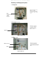
Air RX Link LED
Green LED indicates signal received by the Airlink
receiver. Turns ON at the threshold level.
Air RX Data LED
Yellow LED blinking indicates Data transfer via
the Airlink receiver to the interface.
TP RX Link LED
Green LED indicates Link established at the
100Base-T receiver. Turns ON when connected to
peripheral equipment.
TP RX Data LED
Yellow LED blinking indicates Data transfered via
the 100Base-TX interface.
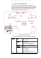
Indicators
(7-segment
display,
LEDs)
Optical Power 7-
segment display
Digital readout indicates the Optical Power level
received by the Airlink receiver.
Alignment Telescope
For fine alignment.
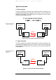
Mode of Operation
(Toggles 1, 2)
Set the Operating Mode
ALIGNMENT = Idle transmitted automatically
NORMAL = Signal received through the TP port is
transmitted through the Airlink TX. Signal received
through the Airlink RX is transmitted through the
TP TX.
LOOPBACK=The Data received by the TP RX is
directly returned through the TP TX
IP address set up
(for Mgt. option)
(Toggle 3)
Used only with the management option. When the
Switch toggle is on OFF position, the TereScope’s
IP address is the default one (shown on the back
panel label: 10.0.0.101). To set a new IP address
please refer to the “IP address setting procedure for
TereScope management card” file in the Manuals
CD. The new IP address is valid only after the
TereScope is powered off and on.
Selectors
(DIP Switch
Toggles)
--
shown in Figure
1.6
Speed
(Toggle 4)
Sets the TereScope to Auto-negotiation mode or to
forced 100 mode:
OFF :
Auto-negotiation, ON: Forced 100